Lifting device for connecting two rotor blade segments of a wind turbine

a technology of lifting device and wind turbine, which is applied in the direction of machines/engines, transportation and packaging, and final product manufacturing, etc., can solve the problems of large rotor blade suspension, large rotor blade change, and significant growth of wind turbines, etc., and achieve the effect of balancing the lifting device and altering the balance of the lifting devi

Active Publication Date: 2014-06-05
PP ENERGY APS
View PDF2 Cites 12 Cited by
  • Summary
  • Abstract
  • Description
  • Claims
  • Application Information

AI Technical Summary

Benefits of technology

[0110]According to a further embodiment, the lifting device may further comprise means for changing the direction of one or more of the cables, lines or wires, by means of which

Problems solved by technology

In recent years wind turbines have grown significantly in size and the outer shape of the rotor blades has changed to a complex structure.
It is not only a problem to transport the large rotor blades to the erection site; also the suspension of these large rotor blades is a problem.
Wind farms are often situated in remote landscapes, on hill-tops or offshore locations; that is, locations that can be difficult to access.
Heavy cranes can cause substantial damage to the ground and access roads.
Large cranes and jack-up rigs are inherently costly, and difficult to transport, deploy, operate and demobilise.
In addition, they can only be deployed in low-level wind conditions.
The geometry and the vulnerability of the blades make it difficult to position and assemble the blade segments and it is necessary to use several cranes, and different techniques for handling ropes, wire etc.
With the increasin

Method used


Image

  • Lifting device for connecting two rotor blade segments of a wind turbine
  • Lifting device for connecting two rotor blade segments of a wind turbine
  • Lifting device for connecting two rotor blade segments of a wind turbine

Examples


Embodiment Construction

[0135]The lifting device and a method for connecting two rotor blade segments will be explained in general with reference to FIGS. 1-4.

[0136]FIGS. 1-4 illustrate the lifting device in a schematic matter.

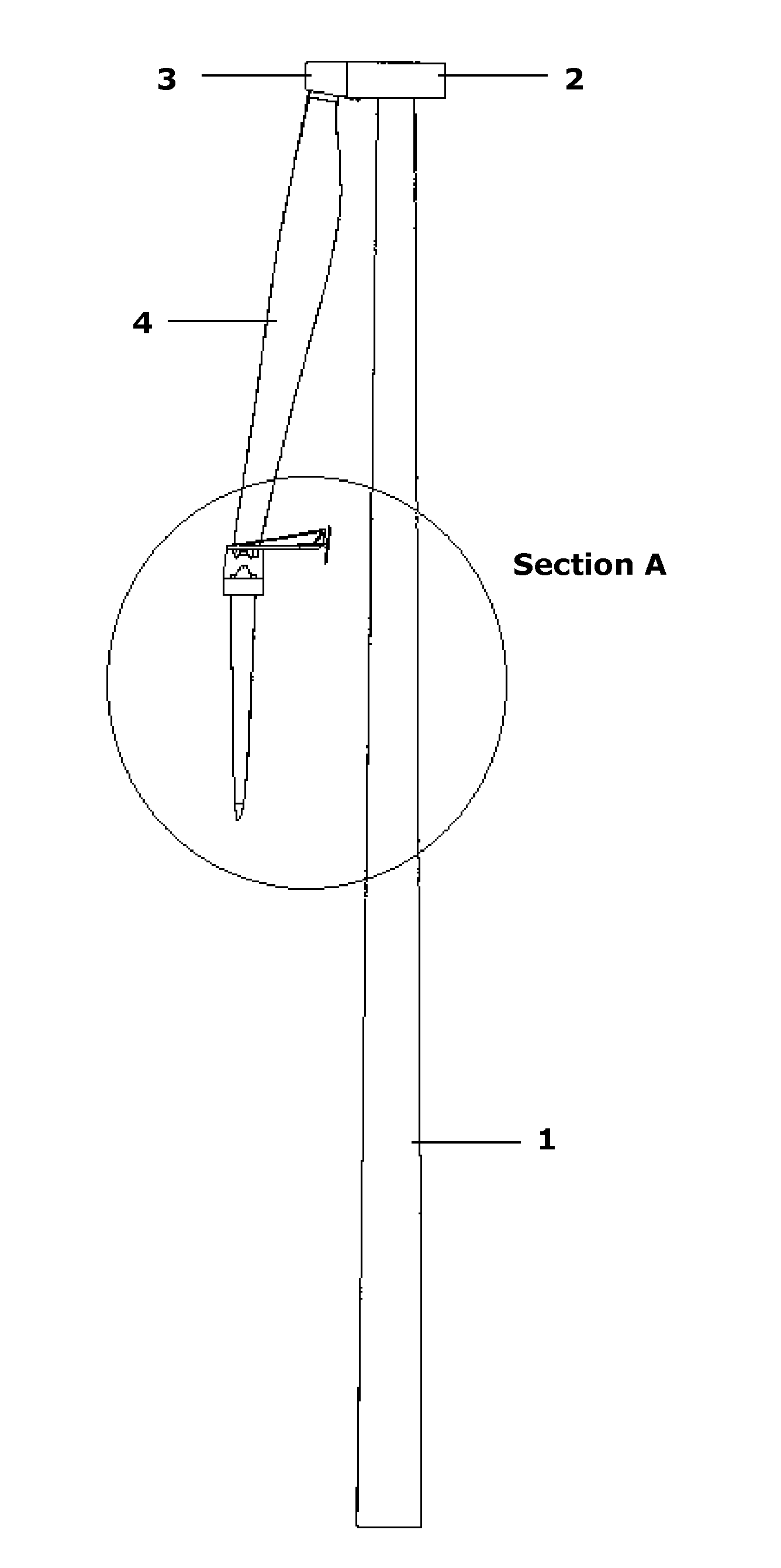
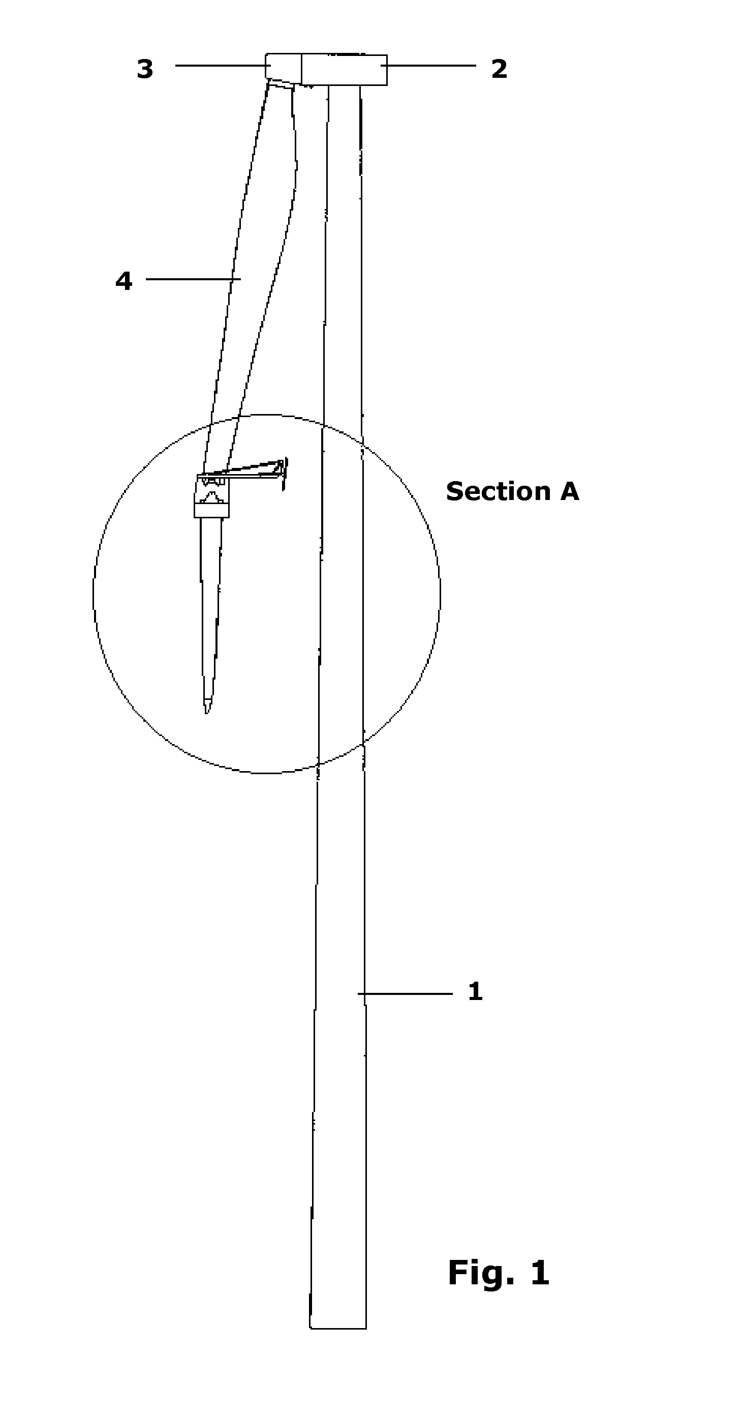
[0137]FIG. 1 discloses a wind turbine tower 1 upon which a nacelle 2 is mounted. From the nacelle 2 extends a non-visible main shaft comprising a hub 3 on which a rotor blade (4) is mounted.

[0138]In the shown situation only one rotor blade 4 is disclosed. The wind turbine is stopped and the rotor blade 4 shown is in an essentially vertical position and has the rear edge of the rotor blade near the tower 1.

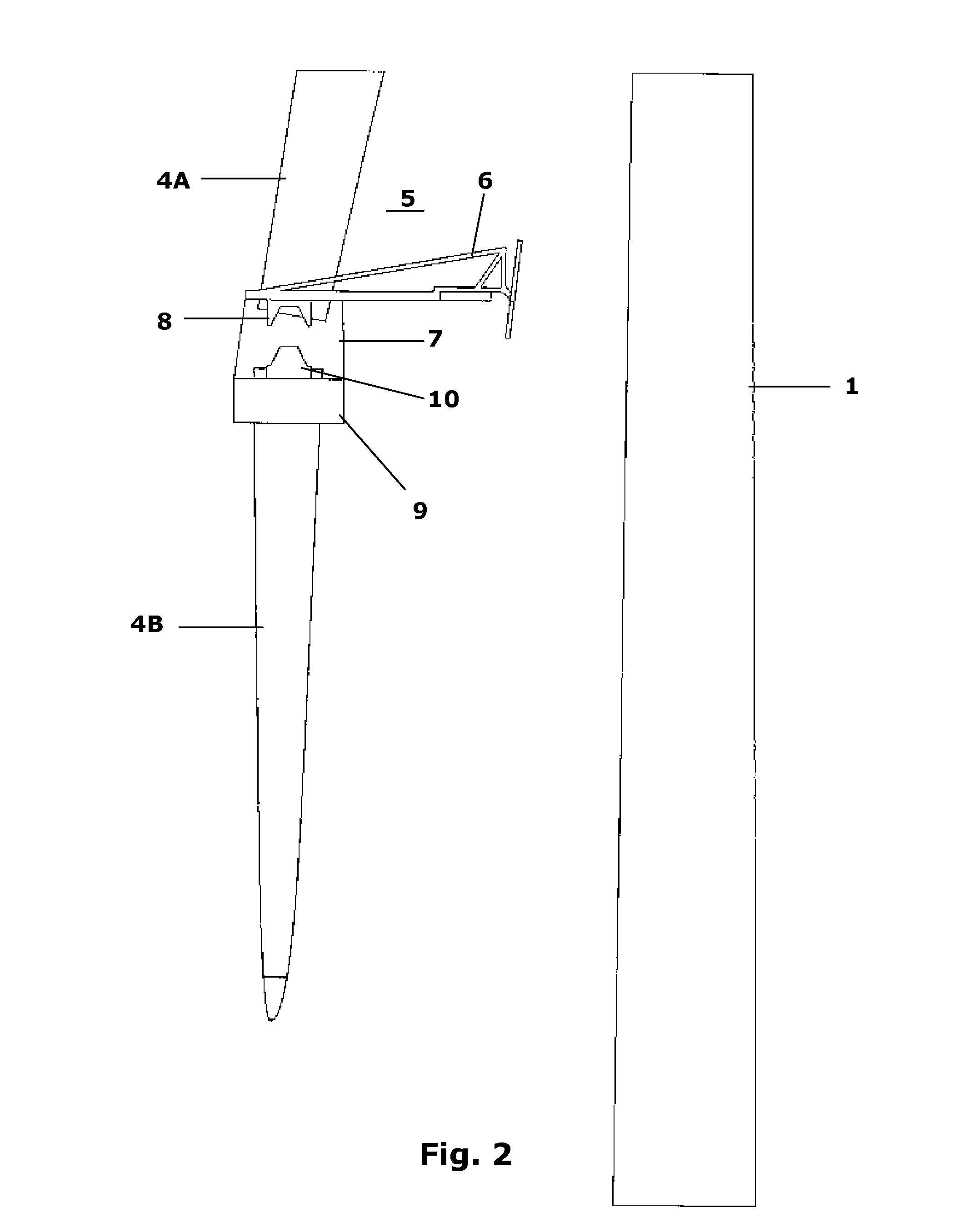
[0139]FIGS. 2-4 illustrate the section A from FIG. 1 where two rotor blade segments 4A and 4B are being connected. The figures present a sequence, showing the method for connecting the rotor blade segments 4A, 4B. The lifting device 5 is lowered down to the end of the first rotor blade segment 4A. The FIGS. 2-4 disclose the frame structure 6, but the means for lowering and / or liftin...


PUM

PropertyMeasurementUnit
Currentaaaaaaaaaa
Digital informationaaaaaaaaaa
Angleaaaaaaaaaa

Abstract

A lifting device 5 for connecting two rotor blade segments 4A, 4B of a wind turbine at the location of the wind turbine, said lifting device 5 being adapted for being moved in the longitudinal direction of the rotor blade, the lifting device comprising:
    • a frame structure 6,
    • means for supporting and guiding the frame structure in relation to the rotor blade,
    • means for lowering and/or lifting the frame structure in relation to the rotor blade,
    • means 7 for lifting and/or lowering a rotor blade segment 4B.

Description

CROSS REFERENCE TO RELATED APPLICATIONS[0001]This application is entitled to the benefit of and incorporates by reference subject matter disclosed in International Patent Application No. PCT / DK2012 / 000065 filed on Jun. 6, 2012, Danish Patent Application No. PA 2011 00440 filed Jun. 9, 2011 and Danish Patent Application No. PA 2011 00866 filed Nov. 8, 2011.FIELD OF THE INVENTION[0002]The present invention relates to a lifting device for guiding the connection of two rotor blade segments of a wind turbine at the location of the wind turbine.[0003]The invention further relates to a lifting assembly for connecting two or more rotor blade segments.[0004]Additionally, the invention relates to a method for connecting two rotor blade segments of a wind turbine.BACKGROUND OF THE INVENTION[0005]The size, shape and weight of rotor blades are factors that contribute to the energy efficiency of wind turbines. An increase in the rotor blade size increases the energy production of a wind turbine, ...

Claims


Application Information

Patent Timeline
IPC IPC(8): F03D11/04F03D1/00
CPCF03D1/001F03D11/04B66C1/108F03D1/0658F03D13/10F03D80/70F05B2230/604F05B2240/302F05B2260/30Y02E10/72Y02P70/50Y10T29/37Y10T29/49337
Inventor TEICHERT, PAUL
Owner PP ENERGY APS
Why Eureka
Try Eureka