Battery system monitoring apparatus

a battery system and monitoring device technology, applied in secondary cells, batteries, instruments, etc., can solve the problems of long measurement time, damage to lithium ion batteries, and inability to normally detect voltage across unit cells, so as to reduce the time for disconnection detection and enhance the safety and reliability of the system.

Active Publication Date: 2014-06-05
HITACHI ASTEMO LTD
View PDF2 Cites 138 Cited by
  • Summary
  • Abstract
  • Description
  • Claims
  • Application Information

AI Technical Summary

Benefits of technology

[0030]With the use of the battery system monitoring apparatus according to the present invention, it can be surely determined whether a multiplexer for selecting a voltage detection target cell operates normally, or not, when measuring the inter-terminal voltages of the unit cells. Also, the disconnection detection can be automatically sequentially conducted without detecting the inter-terminal voltages (cell voltages) of the unit cells at the time of detecting the disconnection. As a result, a time for the disconnection detection can be reduced, and the safety and reliability of the system can be enhanced. Further, the battery system monitoring apparatus can be configured with the use of one cell controller IC without separating the monitoring IC and the control IC from each other.

Problems solved by technology

In particular, in the battery system using a lithium ion battery, when the lithium ion battery is overcharged with a high energy density, there is a possibility that the lithium ion battery is damaged.
If a voltage detection line is not normally connected to each unit cell, the voltage across the unit cell cannot be normally detected.
This voltage measurement circuit resistant to the noise takes a long measurement time for removing a noise component, as a result of which it also takes time to diagnose the disconnection of the voltage detection lines or the voltage measurement system such as the multiplexer, which is conducted by the aid of the voltage measurement.
Also, when the unit cells are selected by the multiplexer, even if the multiplexer operates normally, the summed value of the cell voltages and the total voltage may be different from each other in the interest of synchronism of the cell voltage measurement if a voltage fluctuation is steep, resulting in a possibility of erroneous determination.
In order to conduct the communication through the photocoupler at a high speed, a flowing current at a light emitting diode side needs to increase, and its power supply is supplied from the battery pack, and cannot be increased greatly.
Because the inter-terminal voltage of the cell groups becomes high voltage, a problem of a dark current in the battery monitoring integrated circuit when the vehicle operation stops becomes actualized.

Method used


Image

  • Battery system monitoring apparatus
  • Battery system monitoring apparatus
  • Battery system monitoring apparatus

Examples


first embodiment

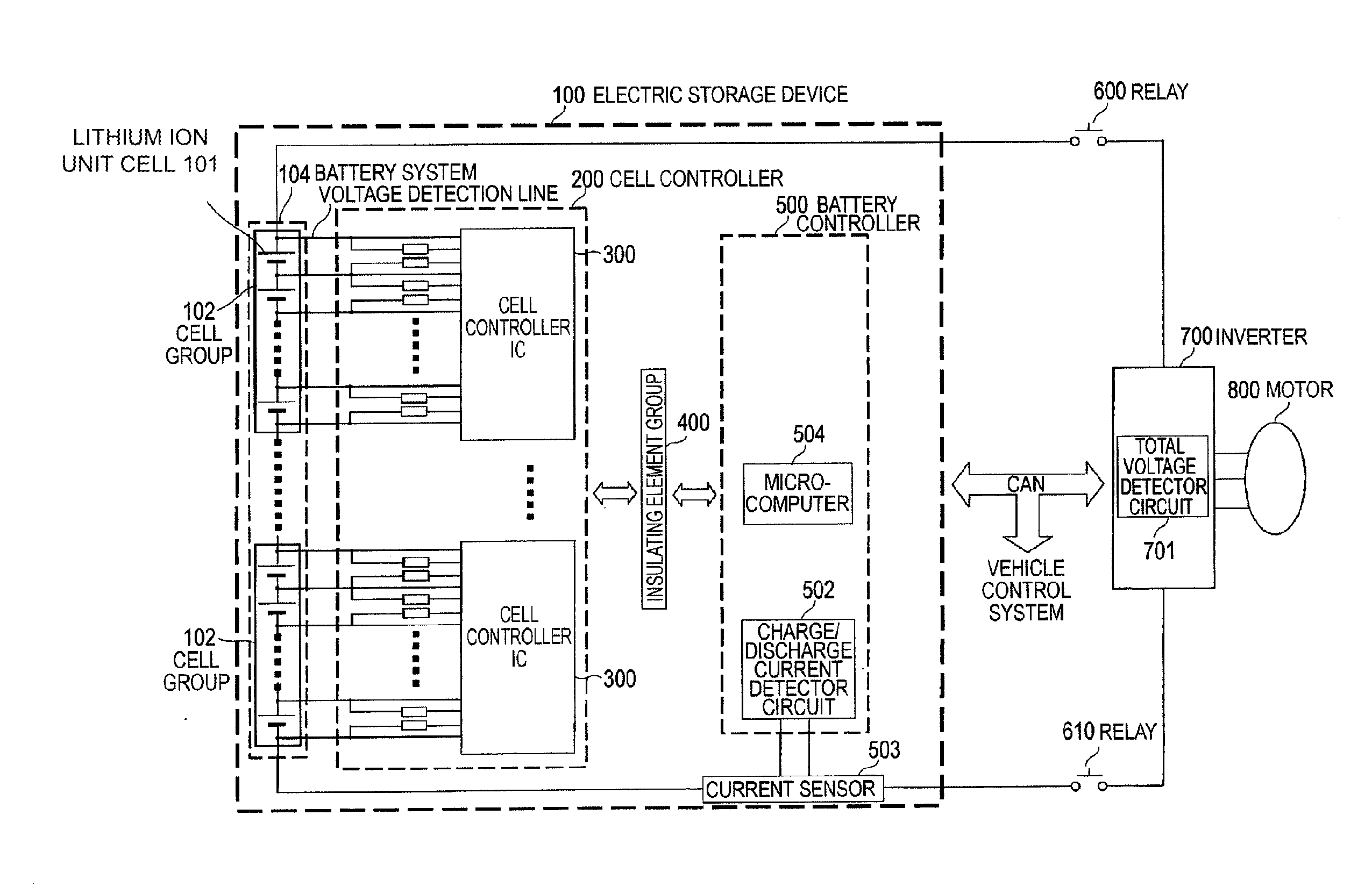
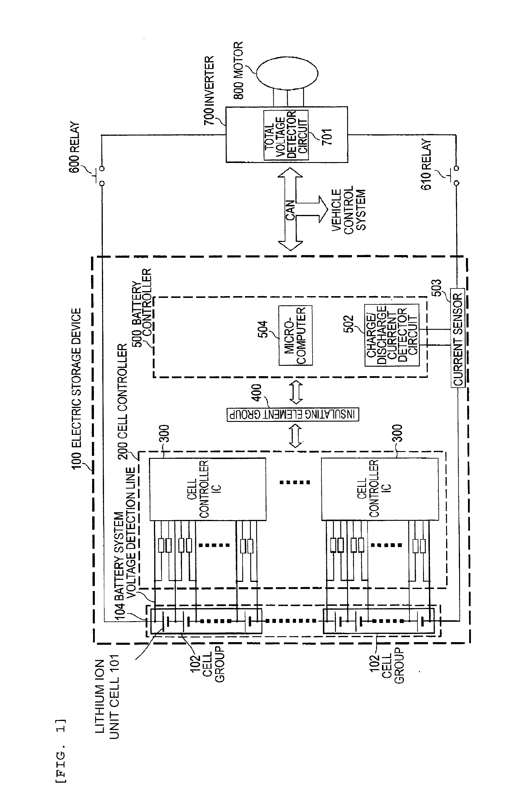
[0068]First, an example in which an electric storage device according to the present invention is applied to a driver system for hybrid electric vehicles will be described.

[0069]An electric storage device 100 is connected to an inverter 700 through relays 600 and 610, and the inverter 700 is connected to a motor 800. When a vehicle starts moving, or accelerates, a discharge power is supplied from the electric storage device 100 to the motor 800 through the inverter 700 to assist an engine not shown. When the vehicle stops or decelerates, a regenerative power is charged into the electric storage device 100 from the motor 800 through the inverter 700. In this example, the inverter 700 includes an inverter circuit having a plurality of semiconductor switching elements, a gate driver circuit of the semiconductor switching elements, and a motor controller that generates a pulse signal for PWM controlling the gate driver circuit. However, those components are omitted from FIG. 1.

[0070]The...

second embodiment

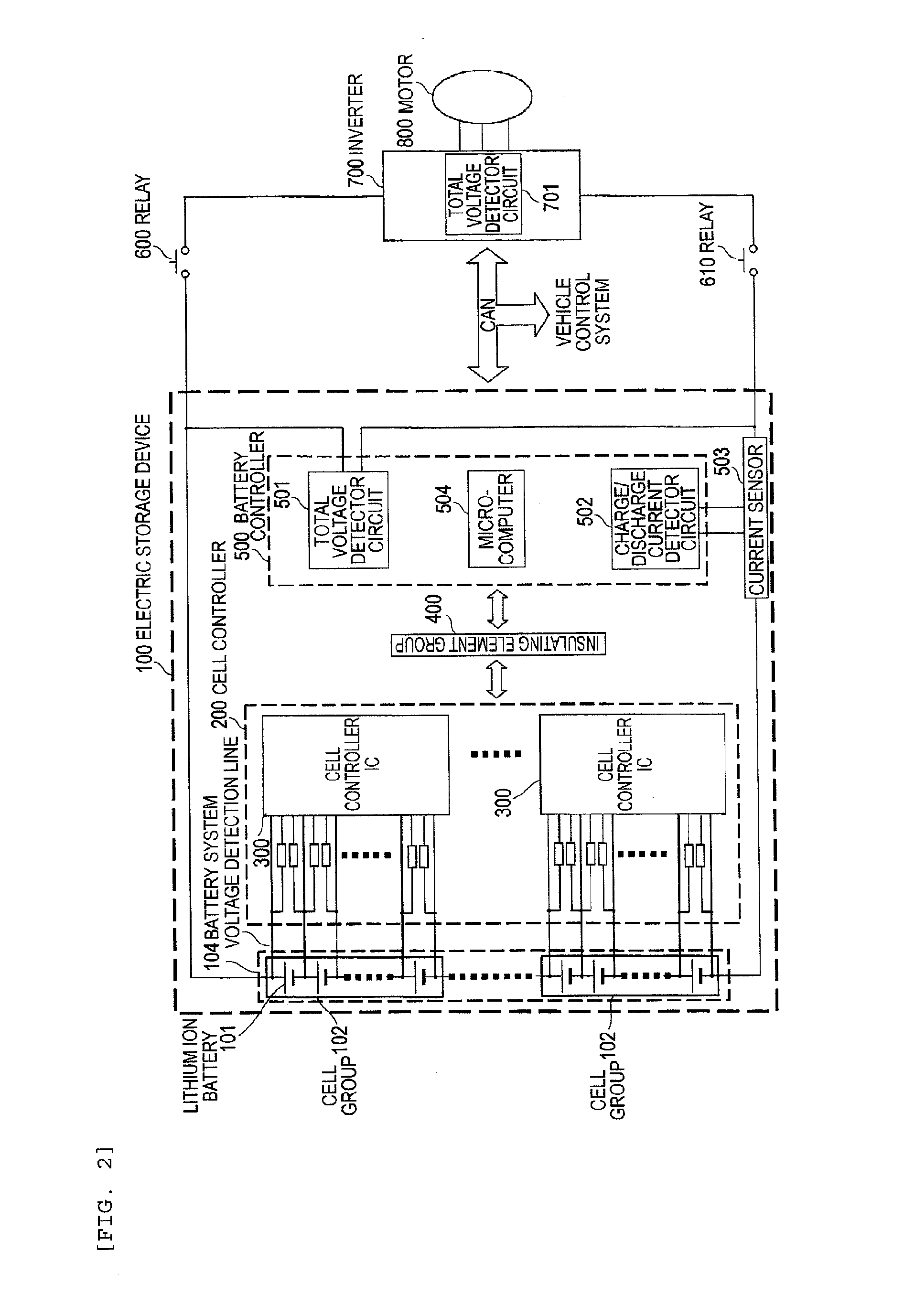
[0383]FIG. 34 illustrates a configuration example of an electric storage device for a hybrid electric vehicle having a battery system monitoring apparatus according to a second embodiment of the present invention. This is an example in which the total voltage detector circuit 501 is also incorporated into the battery controller 500, which corresponds to FIG. 2 illustrating the first embodiment. As described in the first embodiment, if a total voltage of the battery system 104 can be measured in another method, the total voltage detector circuit 501 may not be disposed within the battery controller 500 as illustrated in FIG. 1.

[0384]The electric storage device 100 mainly includes cell groups 102 each having a plurality of lithium ion unit cells 101, a battery system 104 having a plurality of the cell groups 102 connected in series, a cell controller (battery monitoring device) 200 having plural pairs of a main cell controller IC 301 that mainly detects the inter-terminal voltages of ...


PUM


Abstract

A battery system monitoring apparatus that monitors a battery system is provided having a cell group having a plurality of unit cells connected in series, including: a first control device that controls the cell group; and a plurality of voltage detection lines that connect positive electrodes and negative electrodes of the unit cells to the first control device, for measuring inter-terminal voltages of the unit cells. The first control device includes a balancing switch connected between the voltage detection line connected to the positive electrode of each unit cell and the voltage detection line connected to the negative electrode thereof for conducting balancing discharge of the unit cell, for each of the unit cells. A first resistor is disposed in series with each of the voltage detection lines, a first capacitor is connected between the voltage detection line, and a GND which is a lowest-level potential of the cell group.

Description

TECHNICAL FIELD[0001]The present invention relates to a battery system monitoring apparatus.BACKGROUND ART[0002]In hybrid electric vehicles (HEV) and electric vehicles (EV), in order to ensure a desired high voltage, a battery pack (battery system) in which a large number of unit cells in a secondary battery are connected in series with each other is used. In the battery pack thus configured, for the purpose of conducting capacity calculation or protection management of the respective unit cells, the unit cells are managed with the use of a monitoring IC for monitoring a state of the unit cells and a control IC for controlling a charge / discharge state of the unit cells (for example, refer to PTL 1).[0003]In particular, in the battery system using a lithium ion battery, when the lithium ion battery is overcharged with a high energy density, there is a possibility that the lithium ion battery is damaged. For that reason, as disclosed in PTL 2, a voltage across each of the unit cells i...

Claims


Application Information

Patent Timeline
Patent Type & Authority Applications(United States)
IPC IPC(8): B60L11/18B60L3/00G01R19/00H02J7/02G01R31/36H02J7/00
CPCB60L11/1866H02J7/0016H01M10/425H01M10/482H01M2010/4271H01M10/441H01M10/4264H01M2220/20B60L3/0046B60L2240/545B60L2240/547B60L2240/549B60L2200/26G01R31/396G01R31/3835B60L50/51B60L58/14B60L58/22B60L58/15B60L58/24H02J2310/48Y02T10/70Y02T10/7072Y02T90/14Y02E60/10H02J7/0047
Inventor YAMAUCHI, TATSUMIMACHIDA, AKIHIROKUDO, AKIHIKOEMORI, AKIHIKOKIKUCHI, MUTSUMI
Owner HITACHI ASTEMO LTD
Why Eureka
Try Eureka