
Electrode member and touch panel including the same

a technology applied in the field of electrode members and touch panels, can solve the problems of reducing the performance, affecting the realization of fine patterns, and limiting the low resistance required for a large-area touch panel, so as to improve the manufacturing process efficiency of the touch panel having the electrode members applied thereto

Active Publication Date: 2014-06-05
LG INNOTEK CO LTD
View PDF5 Cites 58 Cited by
  • Summary
  • Abstract
  • Description
  • Claims
  • Application Information

AI Technical Summary

Benefits of technology

The patent text describes a touch panel with a transparent electrode that has a very small line width, improving its transparency and visibility. The fabrication method of the panel allows for simultaneous formation of multiple patterns, simplifying the process of forming the wire electrode and the sensing electrode. This results in a more efficient fabrication process and improved touch panel performance.

Problems solved by technology

In the resistive type touch panel, the repeated use thereof may degrade the performance thereof, and cause scratches.
Meanwhile, although indium tin oxide (ITO) has been most extensively used for an electrode of the touch panel, ITO has a limitation in the realization of low-resistance required for a large-area touch panel.
However, in the case of the metal mesh formed through the conventional printing scheme, the realization of a fine pattern is difficult.
The permeability of the metal mesh fabricated in the above scheme is degraded, and the metal lines are viewed, so that a problem occurs in visibility.
However, when the wire electrode pattern and the sensing electrode pattern are formed in the above scheme, the number of processes is increased, and the processes are complex, so that the process efficiency may be reduced.

Method used


Image

  • Electrode member and touch panel including the same
  • Electrode member and touch panel including the same
  • Electrode member and touch panel including the same

Examples


first embodiment

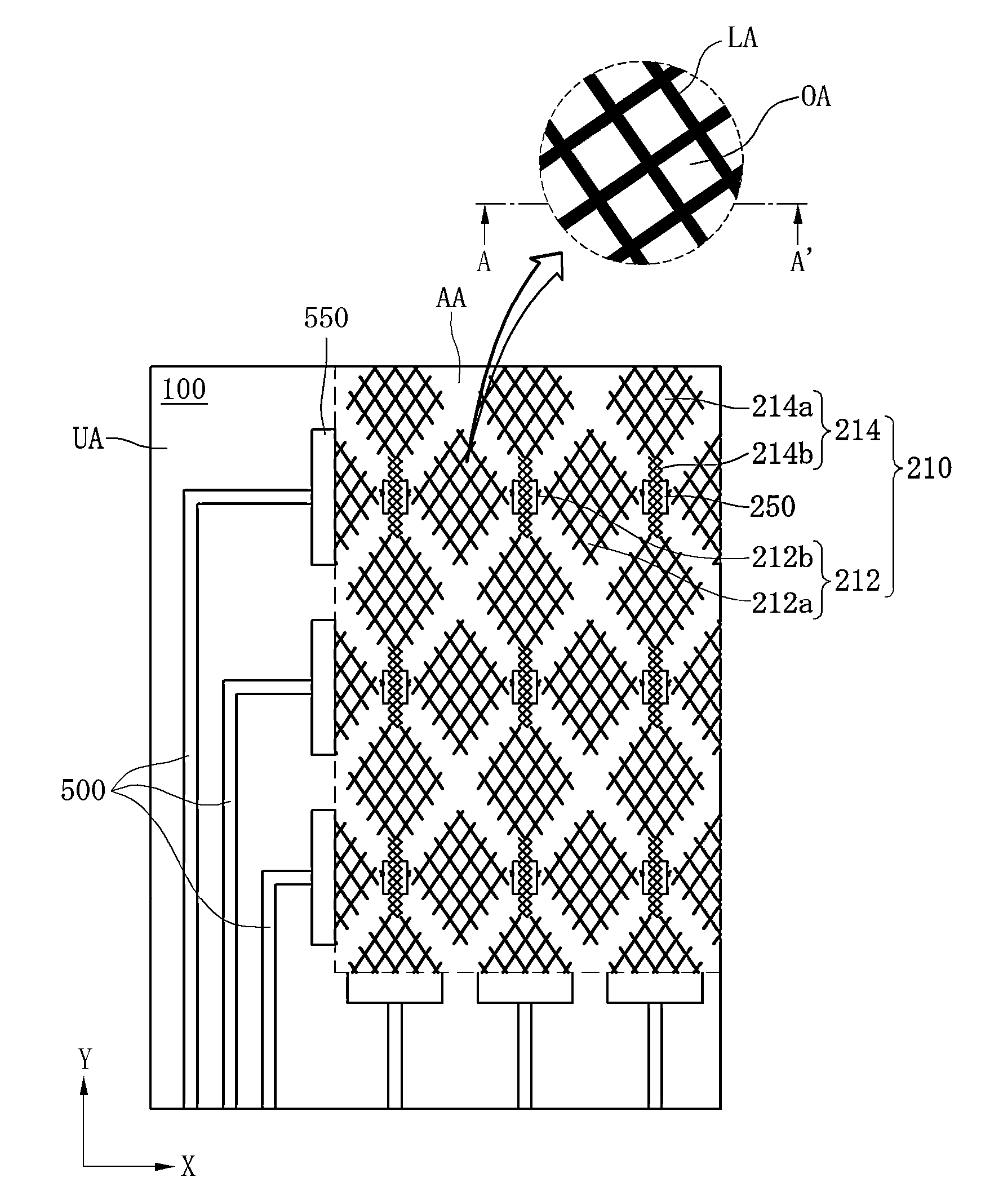
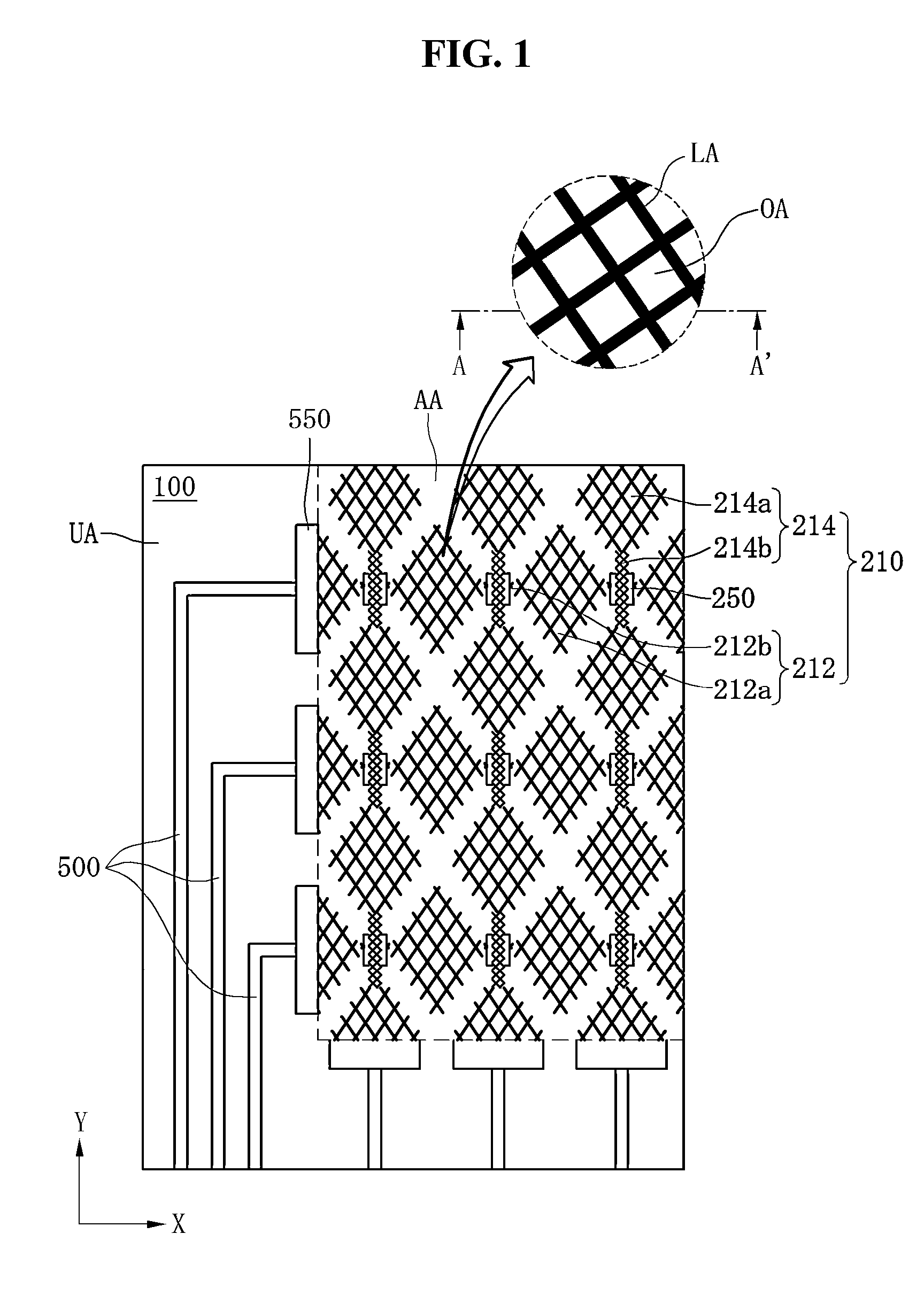
[0129]The touch panel may include the above-described electrode member. In detail, the touch panel according to the embodiment includes a cover window and an electrode member formed on the cover window. The electrode member includes a substrate including an active area and an unactive area, first and second patterns formed on the unactive area, and a first electrode formed on the first pattern. The width of the first pattern may be greater than the width of the second pattern.

[0130]In addition, the electrode member further includes third and fourth patterns formed on the active area, and a second electrode formed on the third pattern. The width of the third pattern may be wider than the width of the fourth pattern.

[0131]In this case, the first and second electrodes may include the same metal material.

second embodiment

[0132]The touch panel includes a cover window including an active area and an unactive area, a wire electrode pattern formed on the unactive area, and a sensing electrode pattern formed on the active area. The wire electrode pattern includes first and second patterns, the sensing electrode pattern includes third and fourth patterns, and the width of the first pattern may be greater than that of the second pattern. In other words, in the touch panel according to the embodiment, the sensing electrode pattern and the wire electrode pattern may be directly formed on the cover window.

[0133]In this case, the sensing electrode pattern and the wire electrode pattern may include the same metal material.

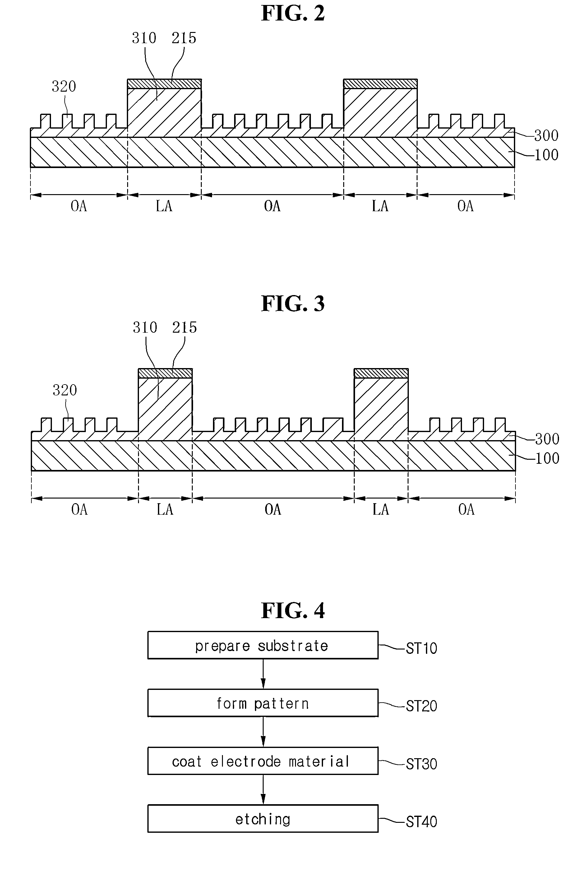
[0134]The touch panel according to the first and second embodiments may include an electrode member described above. Therefore, when forming the sensing electrode and the wire electrode, the process efficiency can be improved, and the fabricating cost can be reduced.

[0135]Any reference in thi...


PUM

PropertyMeasurementUnit
widthaaaaaaaaaa
widthaaaaaaaaaa
widthaaaaaaaaaa

Abstract

Disclosed is a touch panel. The touch panel includes a substrate, and an electrode part formed in a mesh shape on the substrate. The electrode part includes a resin layer comprising first and second sub-patterns, and a transparent electrode on the first sub-pattern. A ratio of a width of the first sub-pattern to a width of the second sub-pattern is in a range of 1:0.01 to 1:0.5.

Description

CROSS-REFERENCE TO RELATED APPLICATIONS[0001]This application claims the benefit under 35 U.S.C. §119 of Korean Patent Application Nos. 10-2012-0138871, filed Dec. 3, 2012, and 10-2013-0083148, filed Jul. 15, 2013, which are hereby incorporated by reference in their entirety.BACKGROUND[0002]The embodiment relates to an electrode member and a touch panel including the same.[0003]Recently, a touch panel, which performs an input function through the touch of an image displayed on a display device by an input device such as a stylus pen or a finger, has been applied to various electronic appliances[0004]The touch panel may be mainly classified into a resistive touch panel and a capacitive touch panel. In the resistive touch panel, glass is shorted with an electrode due to the pressure of the input device so that a touch point is detected. In the capacitive touch panel, the variation in capacitance between electrodes is detected when a finger of the user is touched on the capacitive touc...

Claims


Application Information

Patent Timeline
Patent Type & Authority Applications(United States)
IPC IPC(8): G06F1/16
CPCG06F2203/04103G06F2203/04112G06F3/0445G06F3/0446G06F1/1692
Inventor LEE, YOUNG JAEKIM, HYUN SOOBANG, JUNG HWANSHIN, JUN SIKYANG, JOON HYUKSEONG, DONG MUGEOM, JUN PHILLYOO, KYOUNG JONGLEE, JUNKOO, CHAN KYU
Owner LG INNOTEK CO LTD
Features
  • Generate Ideas
  • Intellectual Property
  • Life Sciences
  • Materials
  • Tech Scout
  • Unparalleled Data Quality
  • Higher Quality Content
  • 60% Fewer Hallucinations
Learn More