
Method of manufacturing a bonded body

a technology of bonded body and bonded body, which is applied in the direction of controlling lamination, process and machine control, mechanical control devices, etc., can solve the problems of increasing reducing the strength of the base material, and reducing the number of processing steps, so as to shorten the time, and reduce the risk of deformation

Inactive Publication Date: 2014-06-05
ORIGIN ELECTRIC CO LTD +1
View PDF6 Cites 16 Cited by
  • Summary
  • Abstract
  • Description
  • Claims
  • Application Information

AI Technical Summary

Benefits of technology

The patent text describes a method for creating a strong bond between two materials made of composite materials (both containing thermoplastic resin and carbon fibers) that requires minimal electricity and results in a minimal amount of deformation. The technical effects of this method are greater strength, durability, and resistance to warping or other forms of deformation.

Problems solved by technology

As for fastening with a bolt-and-nut or a rivet, it is necessary to make a hole in a base material, thereby posing problems such as the reduction of the strength of the base material and an increase in the number of processing steps.
Further, although a carbon fiber composite material is now attracting much attention as a material which brings about the effect of reducing weight due to its strength and lightweight, if the number of positions to be fastened with a bolt-and-nut or a rivet is increased, a merit obtained by using the carbon fiber composite material may be impaired by weight growth due to an increase in the number of fastener parts.
As for conjugation with an adhesive, high conjugation strength is not obtained, and therefore not suitable for a structural body.
However, welding making use of a hot plate has a problem that a resin adheres to the hot plate due to stringing.
As for vibration welding, a special jig is required for each type of workpiece and the bonding surface must be vibrated, therefore making it impossible to handle a complex shape.
Ultrasonic welding has limitation to the size of a horn, cannot handle a large-sized workpiece and has a problem such as the generation of a high-frequency sound.
However, this method has a disadvantage that the composites warp because a unidirectional material of continuous fibers is used as the carbon fibers (page 264, left column).

Method used


Image

  • Method of manufacturing a bonded body
  • Method of manufacturing a bonded body
  • Method of manufacturing a bonded body

Examples


example 1

Composite Material

[0110]Carbon fibers cut to an average fiber length of 20 mm (Tenax STS40 of Toho Tenax Co., Ltd., average fiber diameter of 7 μm) were randomly oriented to ensure that the average weight became 540 g / m2 and the weight ratio of the carbon fibers became 52% and Unitika Nylon 6 of Unitika Ltd. was used as a matrix to prepare a carbon fiber composite material.

(Fixing, Energization)

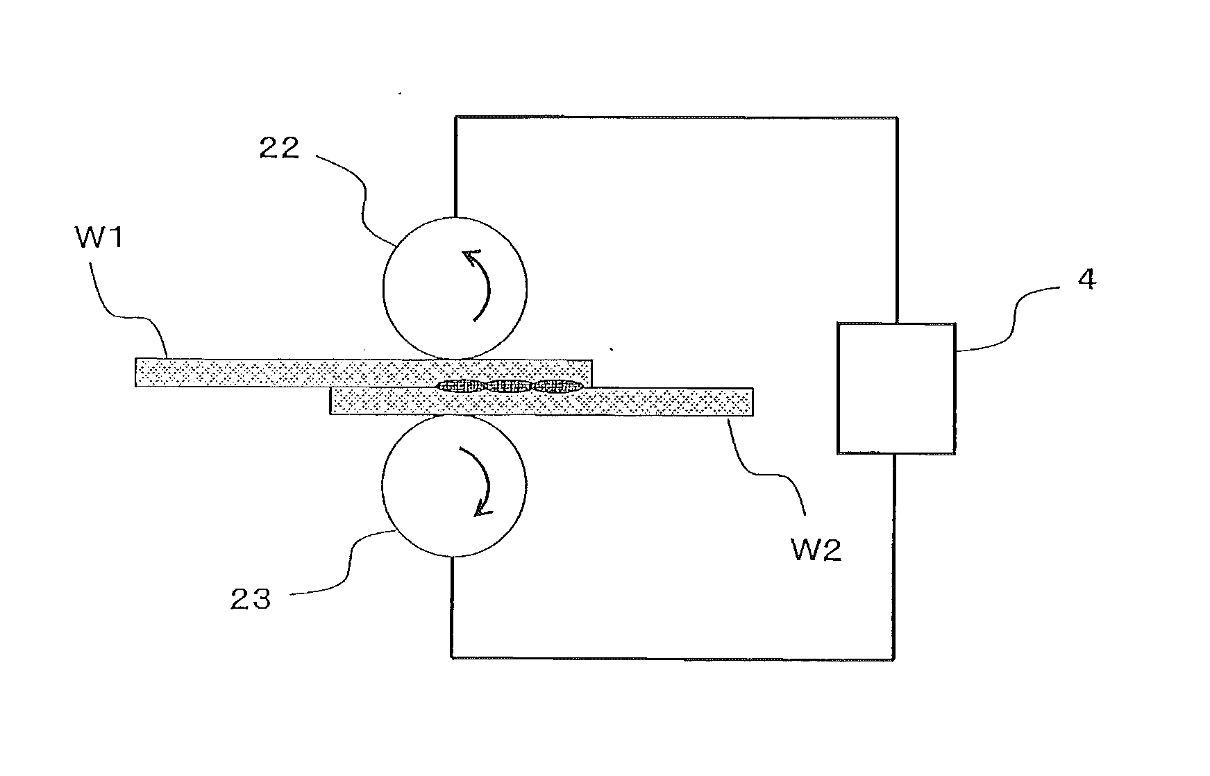
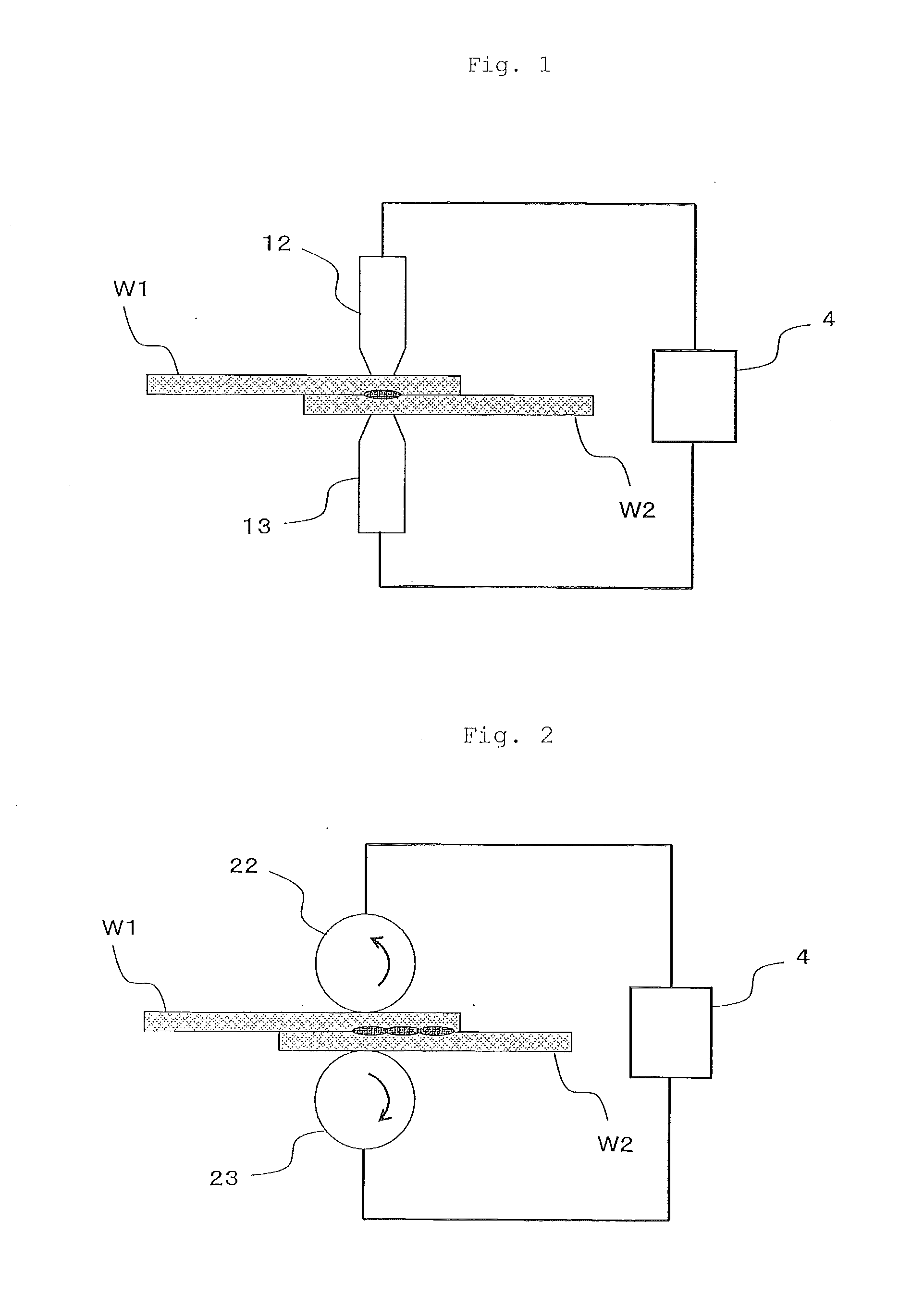
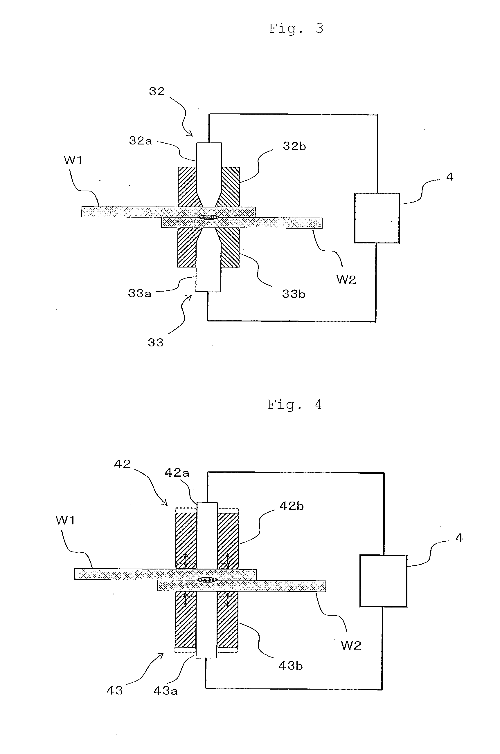
[0111]Two of the composite materials having plate dimensions of 100 mm×25 min×2 mm were prepared and overlapped each other, and the overlapped portion was sandwiched between electrodes. Copper electrodes having an end diameter of 12 mm were used. The welding pressure was set to 6.6 kN (58.4 MPa). A 60 A current was applied from a DC power source for 1 second while the overlapped composite materials were pressurized. The number of bonding points was 1.

(Evaluation)

[0112]When a tensile shear test was made on the obtained bonded body at a speed of 1 mm / min by using the 5587 300 kN floor type univ...

example 2

[0113]Two composite materials of the same type as that of Example 1 were prepared, overlapped each other and sandwiched between copper electrodes having an end diameter of 5 mm. The welding pressure was set to 3.4 kN (173 MPa), and a 60 A current was applied from a DC power source for 2 seconds. The number of bonding points was 1.

(Evaluation)

[0114]When a tensile shear test was made on the obtained bonded body at a speed of 1 mm / min by using the 5587 300 kN floor type universal tester of Instron Co., Ltd., the break strength was 2.77 kN. Deformation such as warp was not observed in the obtained bonded body.

example 3

Composite Material

[0115]Carbon fibers cut to an average fiber length of 20 mm (Tenax STS40 of Toho Tenax Co., Ltd., average fiber diameter of 7 μm) were randomly oriented to ensure that the average weight became 540 g / m2 and the weight ratio of the carbon fibers became 52%, and Unitika Nylon 6 of Unitika Ltd. was used as a matrix to prepare a carbon fiber composite material.

(Fixing, Energization)

[0116]Two of the composite materials having plate dimensions of 100 mm×25 mm×1.5 mm were prepared and overlapped each other, and the overlapped portion was sandwiched between electrodes. A copper electrode having an inner diameter of 7 mm and a pressure aided electrode made of fluororesin and having an outer diameter of 16 mm were used. The welding pressure between the electrodes was set to 5.6 kN (27.9 MPa). Electricity was applied from a DC power source while the composite materials were pressurized. The current value was raised from 5 A to 50 A in first 0.5 second and then maintained at 5...


PUM

PropertyMeasurementUnit
Timeaaaaaaaaaa
Percent by massaaaaaaaaaa

Abstract

A method of obtaining a high-strength bonded body between composite materials, each containing a thermoplastic resin and carbon fibers, with a low current in a short period of time, wherein the bonded body is rarely susceptible to deformation such as warp.The method of manufacturing a bonded body, comprises the steps of:(i) preparing a plurality of composite materials, each containing a thermoplastic resin and discontinuous carbon fibers which are randomly oriented;(ii) overlapping the composite materials each other;(iii) sandwiching at least a part of the overlapped portion between a pair of electrodes; and(iv) applying electricity between the electrodes to weld together the thermoplastic resins with Joule heat.

Description

TECHNICAL FIELD[0001]The present invention relates to a method of manufacturing a bonded body between composite materials, each containing a thermoplastic resin as a matrix and discontinuous carbon fibers.BACKGROUND ART[0002]In general, to bond a composite material containing a thermoplastic resin as a matrix, fastening with a bolt-and-nut or a rivet, an adhesive and welding are employed.[0003]As for fastening with a bolt-and-nut or a rivet, it is necessary to make a hole in a base material, thereby posing problems such as the reduction of the strength of the base material and an increase in the number of processing steps. Further, although a carbon fiber composite material is now attracting much attention as a material which brings about the effect of reducing weight due to its strength and lightweight, if the number of positions to be fastened with a bolt-and-nut or a rivet is increased, a merit obtained by using the carbon fiber composite material may be impaired by weight growth...

Claims


Application Information

Patent Timeline
IPC IPC(8): B29C65/04B32B27/34
CPCB32B27/34B29C65/04B23K11/115B23K11/16B23K11/314B29C65/3416B29C65/3468B29C65/3492B29C66/1122B29C66/1312B29C66/21B29C66/43B29C66/547B29C66/71B29C66/7212B29C66/72143B29C66/73921B29C66/83413B29C66/91655B29C66/919B29C66/929B29C66/949H01B1/24B23K11/061B29C66/91631B29C66/83221B29C66/81875B29C65/38B29C66/73141B29C66/944B29C66/81419B29C66/9241B29C66/8122B29C66/81261B29C66/343B29C66/81463B23K2101/18B23K2103/16B23K2103/172Y10T428/24995Y10T428/31732B29K2023/06B29K2023/12B29K2077/00B29K2081/04B29K2069/00B29K2059/00B29K2025/06B29K2071/12B29K2067/003B29K2067/006B29K2033/12B29K2055/02B29K2307/04B29K2023/04B29K2023/10B29K2025/04B29K2827/18B29K2909/02B29K2067/00B29K2025/08B29C65/02B23K11/06B23K11/00
Inventor KATO, TAKUMISAITO, KIYOSHIKOMATSU, AKIO
Owner ORIGIN ELECTRIC CO LTD
Learn More