Reinforced Catheter Transition With Flexible Tip Portion

a flexible tip and catheter technology, applied in the field of catheters, can solve the problems of affecting the torque transmission, kinks at the distal end or tip of the catheter, unwanted bending, etc., to achieve the effect of improving handling characteristics, improving structural arrangement, and promoting low friction and ease of tracking

Inactive Publication Date: 2014-06-12
VOLCANO CORP
View PDF11 Cites 17 Cited by
  • Summary
  • Abstract
  • Description
  • Claims
  • Application Information

AI Technical Summary

Benefits of technology

The present invention provides improved structural arrangements for the distal portion of intravascular devices, including ultrasound imaging devices. The constructions of the present invention result in devices that have better handling and resistance to kinking or prolapse when introduced through difficult regions of blood vessels. The invention includes a sheath with a flexible tip that prevents prolapse and a thermally bonded catheter junction that strengthens the transition between two shaft portions. The methods also include using a heat shrink thermoplastic sleeve to further strengthen the bond joint. Overall, this invention promotes better performance and smooth transition over the entire length of the bond junction.

Problems solved by technology

Among the difficulties sometimes encountered with short tipped guide wire catheters is the possibility that the distal end or tip of the catheter may kink as it is advanced through the patient's vasculature.
The unwanted bending may occur in the region of a guide wire side port, irrigation port, or any unsupported region distal region of the imaging system sheath.
Higher friction will be encountered at the location of the kink, adversely affecting torque transmission, as well as making it more difficult to advance the catheter over the guide wire.
One difficulty has been that catheter junctions often result in a lump, step, or other surface irregularity in the bond junction.

Method used


Image

  • Reinforced Catheter Transition With Flexible Tip Portion
  • Reinforced Catheter Transition With Flexible Tip Portion
  • Reinforced Catheter Transition With Flexible Tip Portion

Examples


Embodiment Construction

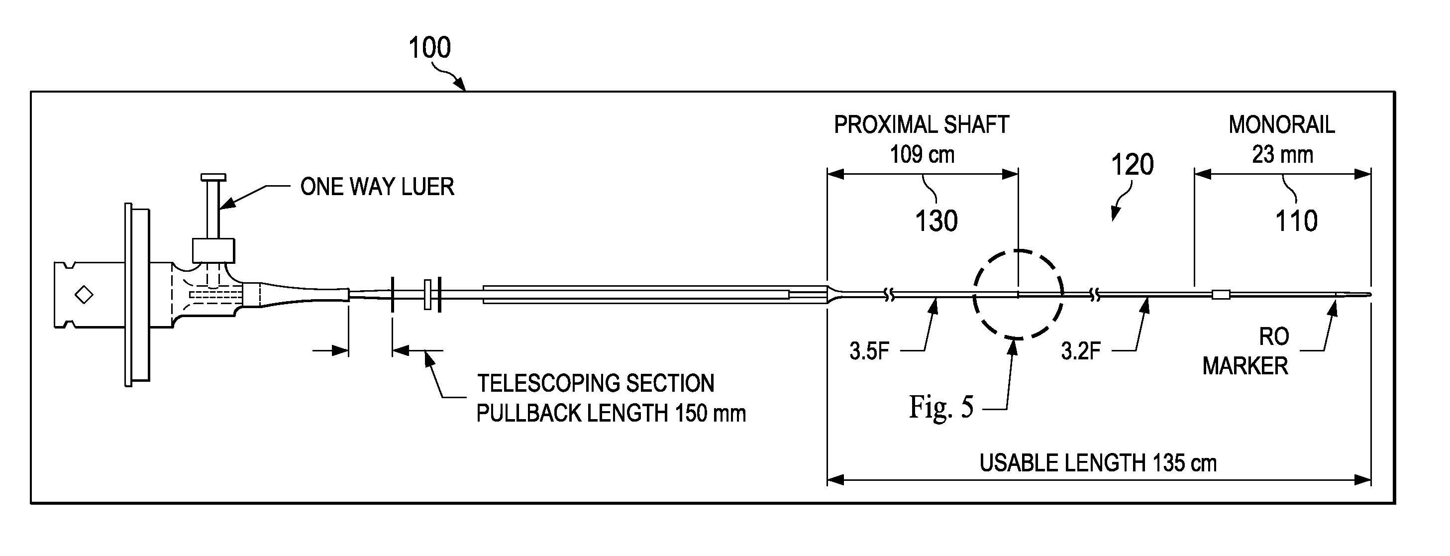
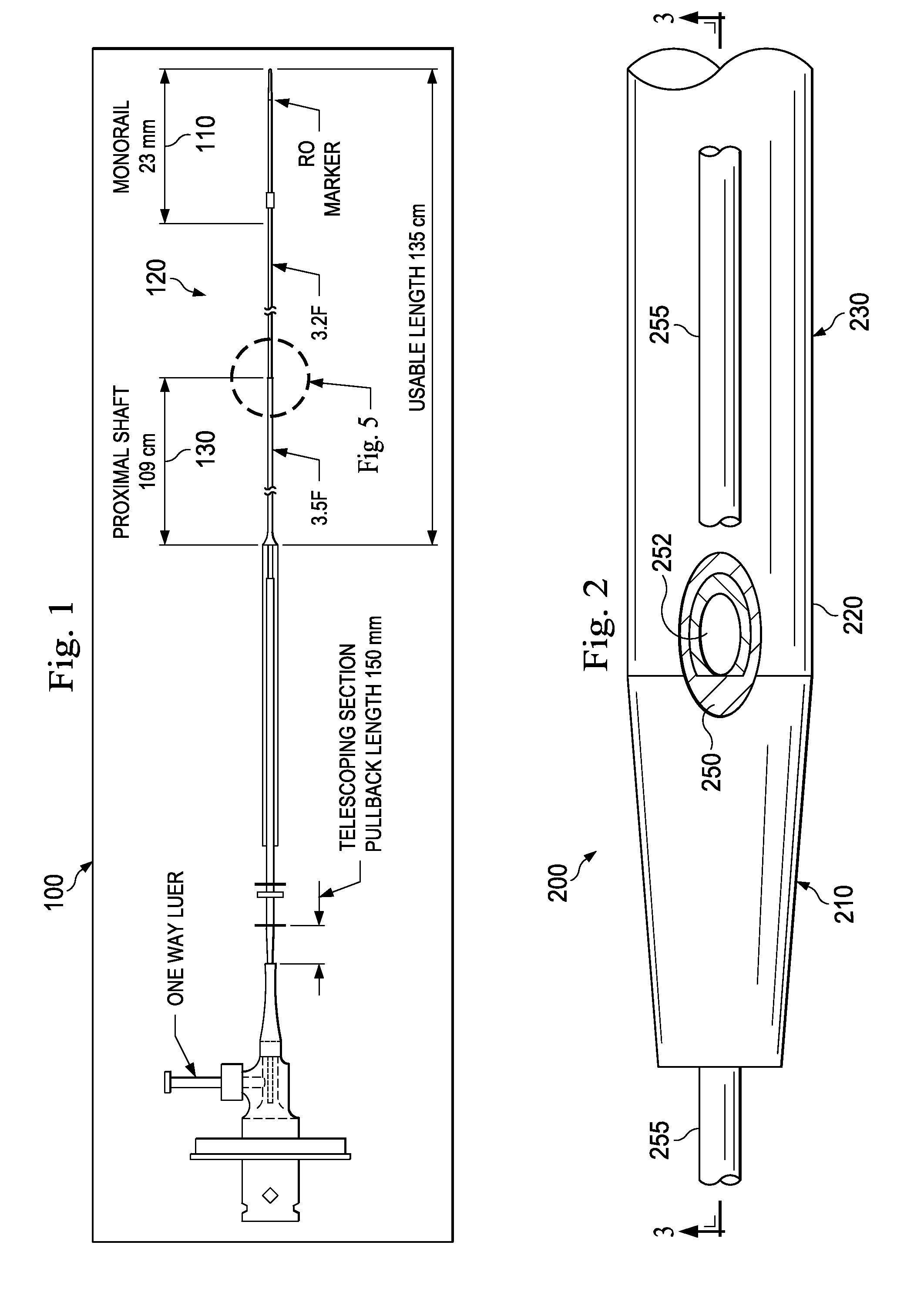
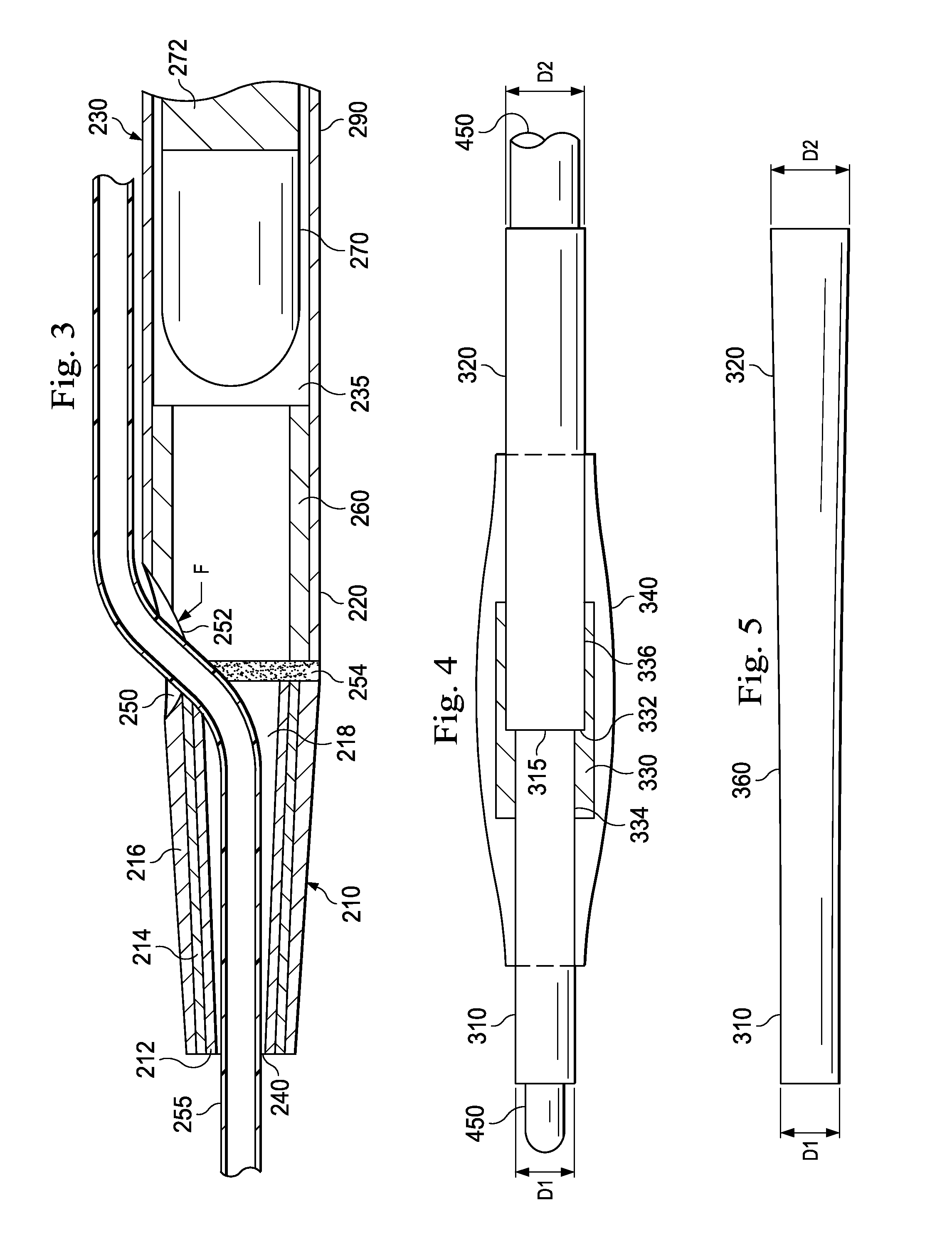
[0019]For the purposes of promoting an understanding of the principles of the present disclosure, reference will now be made to the embodiments illustrated in the drawings, and specific language will be used to describe the same. It is nevertheless understood that no limitation to the scope of the disclosure is intended. Any alterations and further modifications to the described devices, systems, and methods, and any further application of the principles of the present disclosure are fully contemplated and included within the present disclosure as would normally occur to one skilled in the art to which the disclosure relates. In particular, it is fully contemplated that the features, components, and / or steps described with respect to one embodiment may be combined with the features, components, and / or steps described with respect to other embodiments of the present disclosure. For the sake of brevity, however, the numerous iterations of these combinations will not be described separ...


PUM

PropertyMeasurementUnit
lengthaaaaaaaaaa
lengthaaaaaaaaaa
diameteraaaaaaaaaa

Abstract

The present disclosure provides various embodiments of a sheath for a rotational intravascular probe for insertion into a vasculature. An exemplary sheath includes a flexible portion having a lumen for receiving an ultrasound probe, a distal portion that includes a flexible multi-layer tip, and a transition portion that couples the proximal portion and the distal portion. The multi-layer tip defines a guide wire lumen having a distal guide wire opening and a proximal guide wire opening through a sidewall. In some embodiments, an area between the proximal guide wire entry opening and the flexible proximal portion is supported to prevent kinking and prolapse.

Description

CROSS-REFERENCE TO RELATED APPLICATIONS[0001]The present application claims priority to and the benefit of U.S. Provisional Patent Application No. 61 / 734,286, filed Dec. 6, 2012, which is hereby incorporated by reference in its entirety.TECHNICAL FIELD[0002]The present disclosure relates generally to catheters for navigating through the human vasculature, and in particular, to improved catheter tip designs and reinforced sections of the catheter.BACKGROUND[0003]Intravascular ultrasound (IVUS) imaging is widely used in interventional cardiology as a diagnostic tool for assessing a vessel, such as an artery, within the human body to determine the need for treatment, to guide intervention, and / or to assess its effectiveness. An IVUS imaging system uses ultrasound echoes to form a cross-sectional image of the vessel of interest. Typically, IVUS imaging uses a transducer carried by an IVUS catheter that both emits ultrasound signals (waves) and receives the reflected ultrasound signals. ...

Claims


Application Information

Patent Timeline
Patent Type & Authority Applications(United States)
IPC IPC(8): A61M25/01B29C65/02A61M25/00
CPCA61M25/01B29C65/02A61M25/0067A61B8/12A61M25/0009A61L29/041A61L29/085A61L2400/10A61L2420/08A61B8/0891A61B8/445B29C65/68B29C66/1122B29C66/5221B29C66/52292B29L2031/7542B29C66/828B29C66/723B29C66/71B29C66/63C08L23/06C08L51/06C08L77/00B29K2077/00B29K2071/00B29K2023/065B29K2023/06
Inventor VAN HOVEN, DYLAN
Owner VOLCANO CORP
Why Eureka
Try Eureka