

Fuel gas heating with thermal energy storage
a fuel gas heating and thermal energy storage technology, applied in the field of fuel gas heating, can solve the problems of a significant amount of time before one of these power plant components, the total amount of harmful emissions is smaller, and the use of fuel gas heating systems is limited
- Summary
- Abstract
- Description
- Claims
- Application Information
AI Technical Summary
Benefits of technology
Problems solved by technology
Method used
Image

Examples
first embodiment
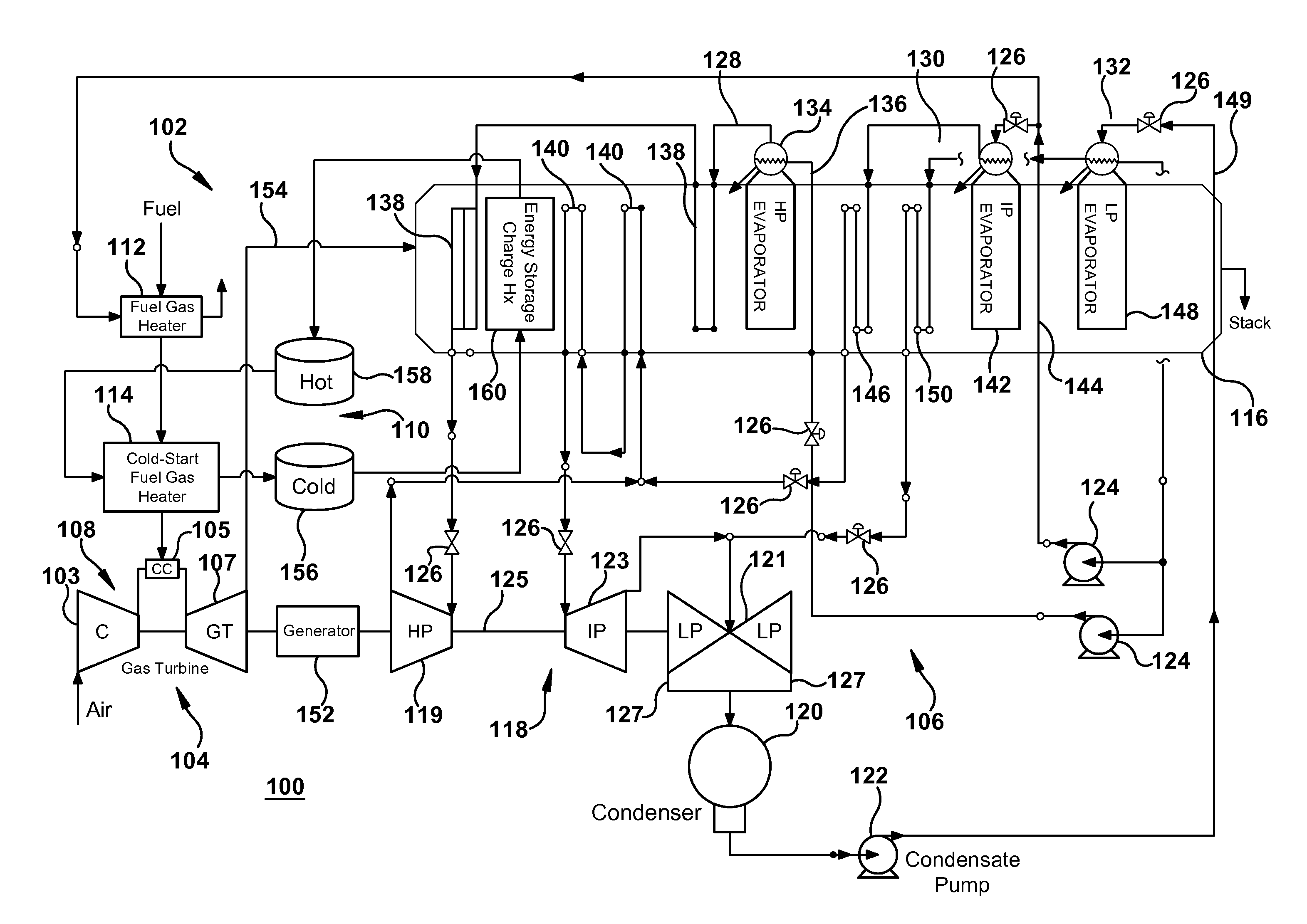
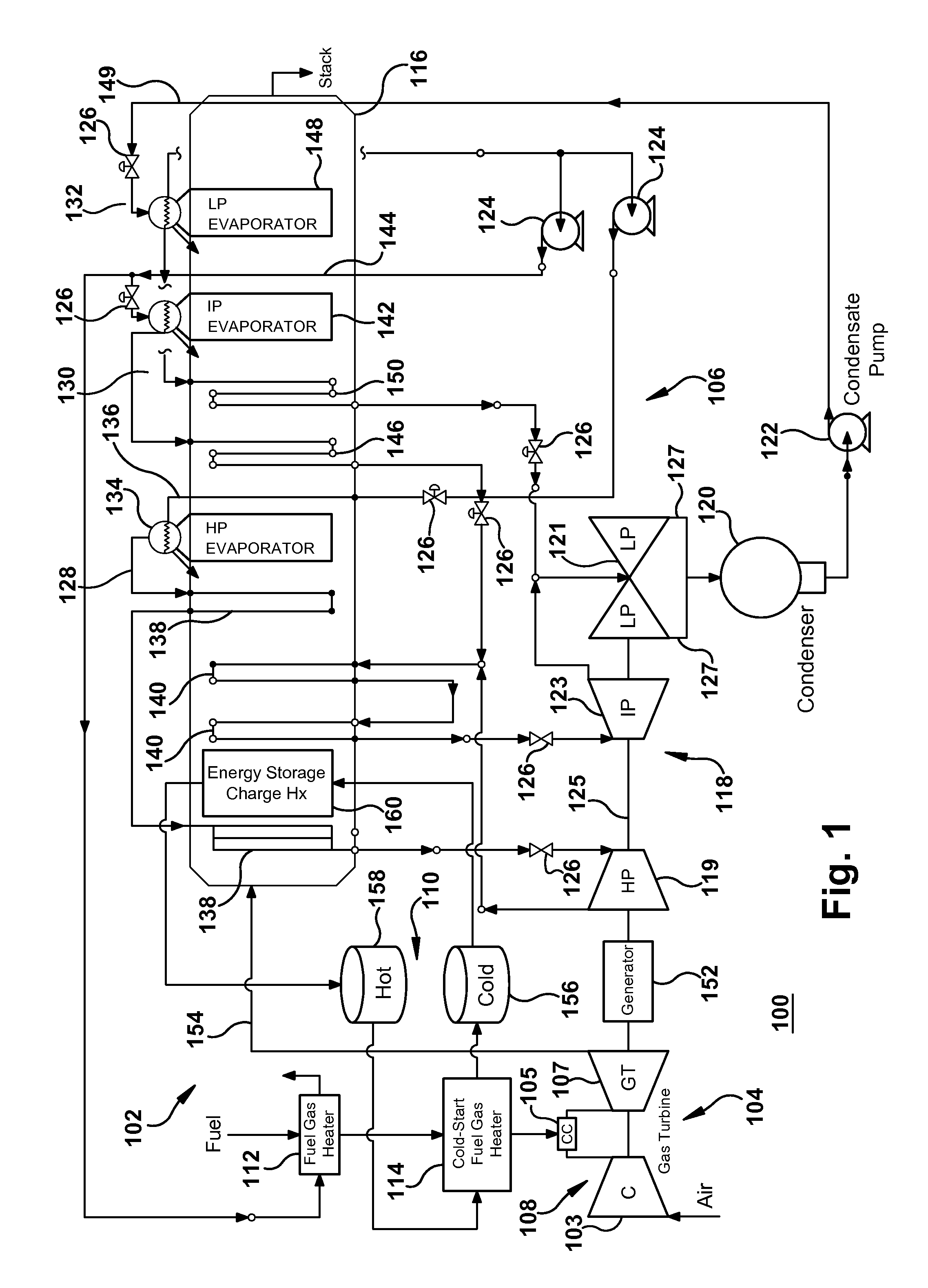
[0014]Referring now to the figures, FIG. 1 shows a schematic diagram of an electrical power generation plant 100 having a fuel gas heating system 102 according to the present invention. The electrical power generation plant 100 illustrated in FIG. 1 is a combined-cycle power plant that includes a top cycle heat engine 104 operating with a topping thermodynamic cycle that is configured to generate electric energy and a bottom cycle heat engine 106 operating with a bottoming thermodynamic cycle that is configured to generate additional electric energy. Although the description that follows pertains to a combined-cycle power plant, those skilled in the art will appreciate that the various embodiments of the present invention may be suitable for any type of power plant that utilizes a gas turbine engine such as, for example, a simple-cycle power plant.
[0015]As shown in FIG. 1, top cycle heat engine 104 includes a gas turbine engine 108 including a compressor section (C) 103, a combustor...
second embodiment
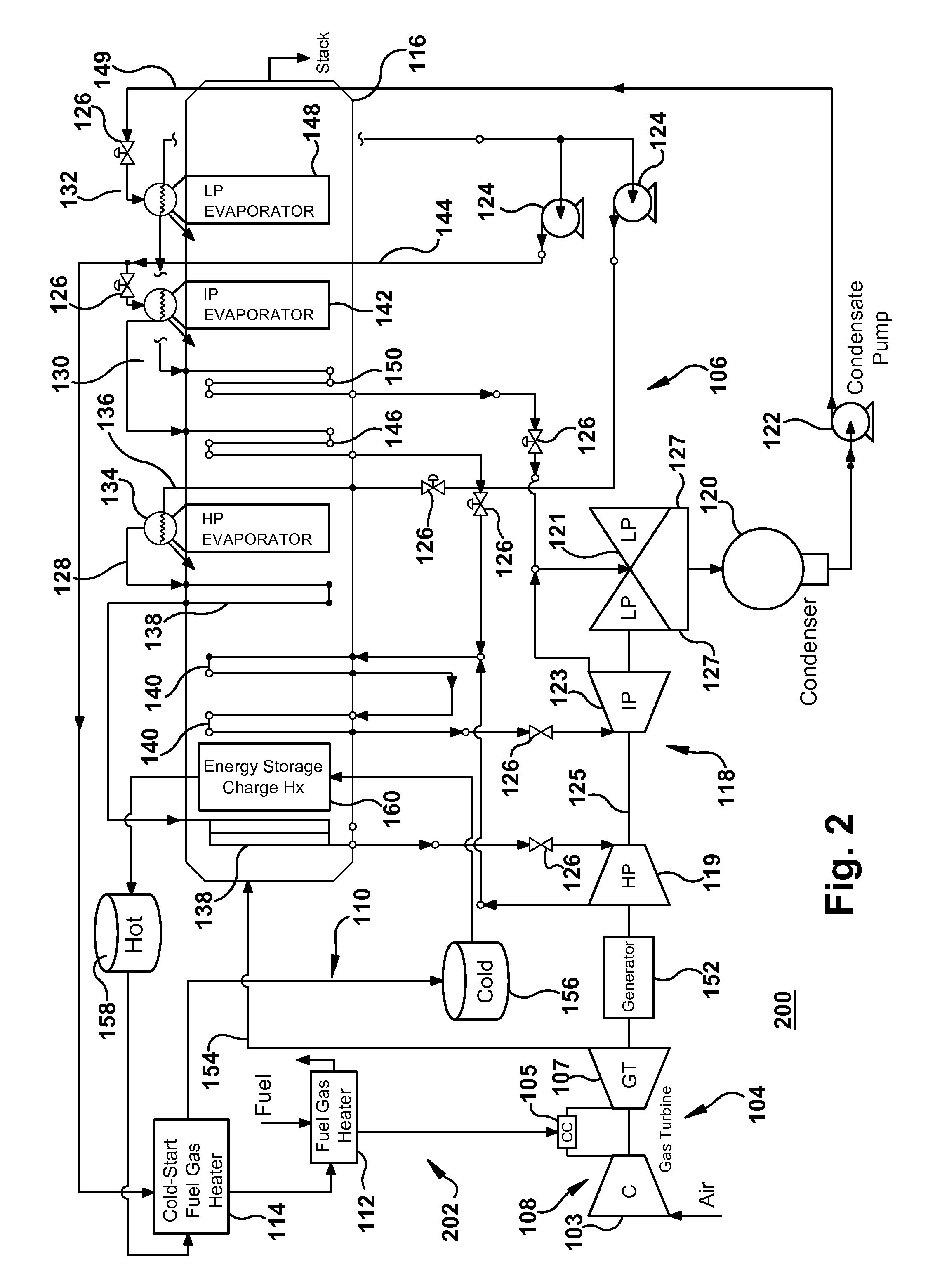
[0034]FIG. 2 shows a schematic diagram of an electrical power generation plant 200 having a fuel gas heating system 202 according to the present invention. In the embodiment illustrated in FIG. 2, fuel gas heater 112 is juxtaposed with cold-start fuel gas heater 114, such that the function of the cold-start fuel heater changes from a “finishing” gas heater to a heat exchanger that warms up the portion of working fluid extracted from HRSG 116, while fuel gas heater 112 acts as the finishing gas heater. In FIG. 2, cold-start fuel gas heater 114 can heat up the portion of working fluid extracted from HRSG 116 to an increased temperature with the thermal storage working medium in hot tank 158 of thermal storage unit 110. In one embodiment, the working fluid applied to cold-start fuel gas heater 114 may be hot water extracted from IP economizer 144. Although FIG. 2 shows cold-start fuel gas heater 114 facilitating a heat transfer between the thermal storage working medium in hot tank 158...
third embodiment
[0038]FIG. 3 shows a schematic diagram of an electrical power generation plant 300 having a fuel gas heating system 302 according to the present invention. In the embodiment illustrated in FIG. 3, fuel gas heater 112 and cold-start fuel gas heater 114 are in the same positions as illustrated in FIG. 2. However, in this embodiment, the energy storage charge heat exchanger 160 has been removed. In FIG. 3, cold-start fuel gas heater 114 can heat up the portion of working fluid extracted from HRSG 116 to an increased temperature with the thermal storage working medium in hot tank 158 of thermal storage unit 110. In one embodiment, the working fluid applied to cold-start fuel gas heater 114 may be hot water extracted from IP economizer 144. Although FIG. 3 shows cold-start fuel gas heater 114 facilitating a heat transfer between the thermal storage working medium in hot tank 158 and hot water extracted from IP economizer 144, the cold-start fuel heater could use the thermal storage mediu...
PUM
 Abstract
Description
Claims
Application Information