Coupled air-conditioning device

a technology of air conditioner and compressor, which is applied in the field of refrigerating air conditioner, can solve the problems of saving energy consumption for moisture removal, and achieve the effects of high refrigeration efficiency, lower power consumption of compressor, and higher refrigeration efficiency of vapor compression-type refrigeration system

Active Publication Date: 2014-06-19
MA JUN
View PDF4 Cites 21 Cited by
  • Summary
  • Abstract
  • Description
  • Claims
  • Application Information

AI Technical Summary

Benefits of technology

[0007]The further objective of the invention is to facilitate latent load and sensible load to be operated separately. A vapor compression-type refrigeration system is not needed to be responsible for removing the moisture from air. Therefore, the vapor compression-type refrigeration system saves the energy consumption for moisture remove. Meanwhile, the evaporation temperature of refrigeration in coupled system can be much higher than the evaporation temperature in a normal vapor compression-type refrigeration system so the refrigeration efficiency can be about 30% higher than that of the common vapor compression-type refrigeration system.
[0010]In a class of this embodiment, the flow rate of the front regeneration air blower is larger than that of the regeneration air blower. The heat-exchange area of the phase-change condensation heat exchanger is larger than that of the refrigerant gas cooler. The air flow rate of the front regeneration air blower is adjusted and controlled by a temperature measurement and controlling device. The front regeneration air blower facilitates the air to flow through the phase-change condensation heat exchanger, and then a portion of the air is regarded as waste hot air and discharged from the exhaust port between the phase-change condensation heat exchanger and the refrigerant gas cooler to the atmosphere. The regeneration air blower facilitates a portion of the air heated by the phase-change condensation heat exchanger to continuously flow through the refrigerant gas cooler to be heated further, thus obtaining high-temperature air.
[0018]The invention facilitates the vapor compression-type refrigeration system and the desiccant-wheel to carry out joint operation. The refrigerant is cooled to be under overcooled state, in the meanwhile, hot air with the temperature of over 70° C. be obtained from the refrigeration system and the hot air be used to regenerate the desiccant wheel. With the provided positions of various parts of the refrigeration system and the dehumidification system, the latent heat load and the sensible heat load are separately processed. Because the refrigeration system is not needed to be responsible for removing the moisture from the air, the evaporation temperature of the refrigeration system can be higher than that of the common refrigeration system. When the evaporation temperature of the refrigeration system can be 2-10° C. higher than that of the common refrigeration system, the ratio of the evaporation pressure to the condensation pressure of the vapor compression-type refrigeration system will become lower, the power consumed by the compressor become lower, and the refrigeration efficiency of the vapor compression-type refrigeration system become higher.
[0019]The flow rate of the front regeneration air blower is larger than that of the regeneration air blower. The energy produced in condensation process of the common refrigeration is larger than the cooling capacity of the refrigeration process. In order to guarantee the enough high refrigeration efficiency, the air flow rate used for cooling the condenser will more than one time that passing through the evaporator. However, in order the desiccant-wheel works effectively, the air flow rate passing through the processing area is generally more than 3 times that passing through the regeneration area. Specially designed flow chart and distribution of the air flow rate guarantees the refrigeration efficiency of the system and the dehumidification efficiency of the desiccant-wheel reach as high as possible at the same time.

Problems solved by technology

Therefore, the vapor compression-type refrigeration system saves the energy consumption for moisture remove.

Method used


Image

  • Coupled air-conditioning device
  • Coupled air-conditioning device
  • Coupled air-conditioning device

Examples


Embodiment Construction

[0030]For further illustrating the invention, experiments detailing a coupled air-conditioning device are described below. It should be noted that the following examples are intended to describe and not to limit the invention.

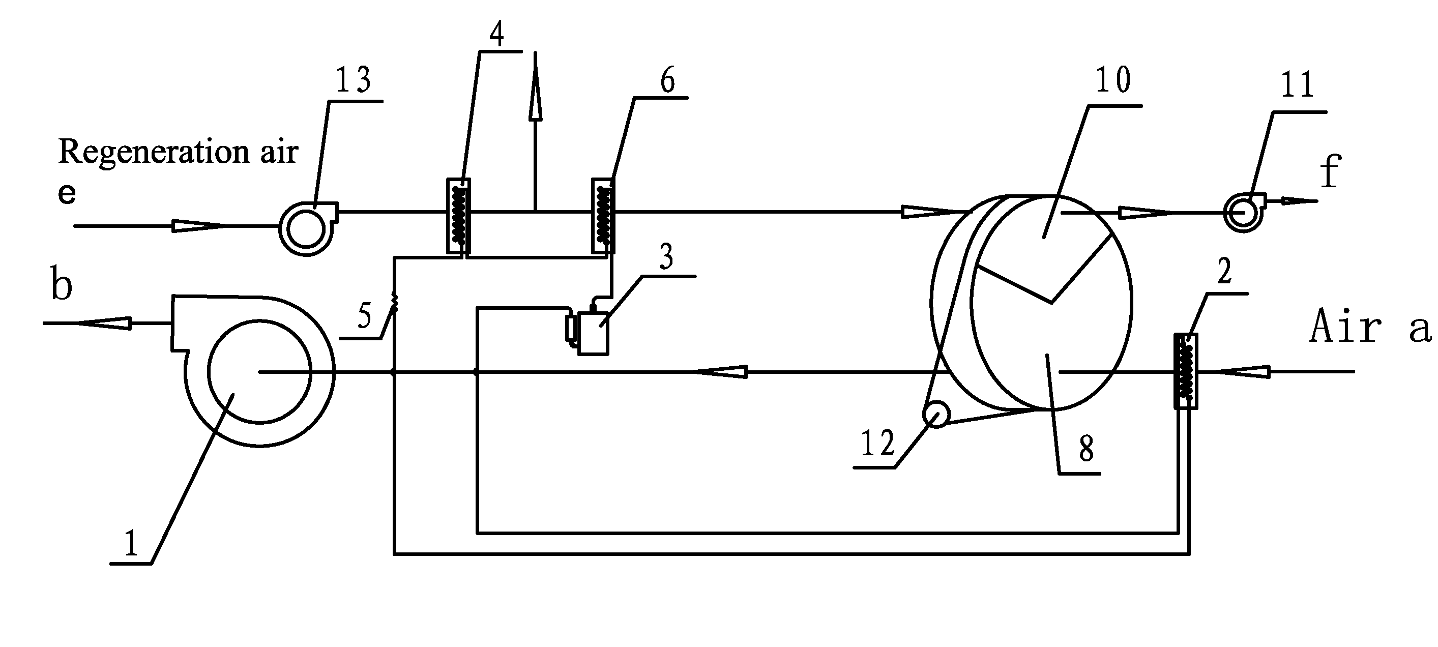
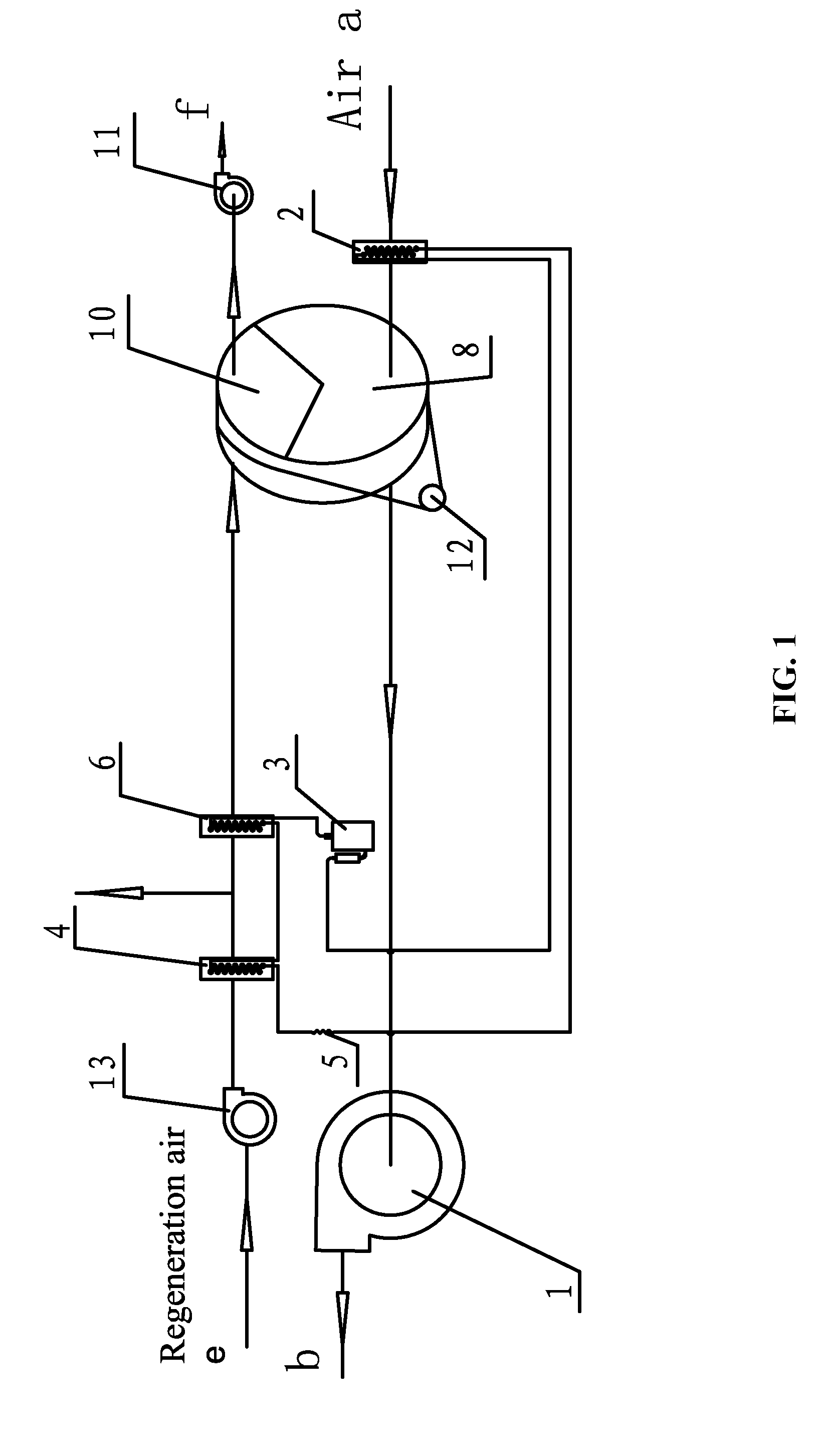
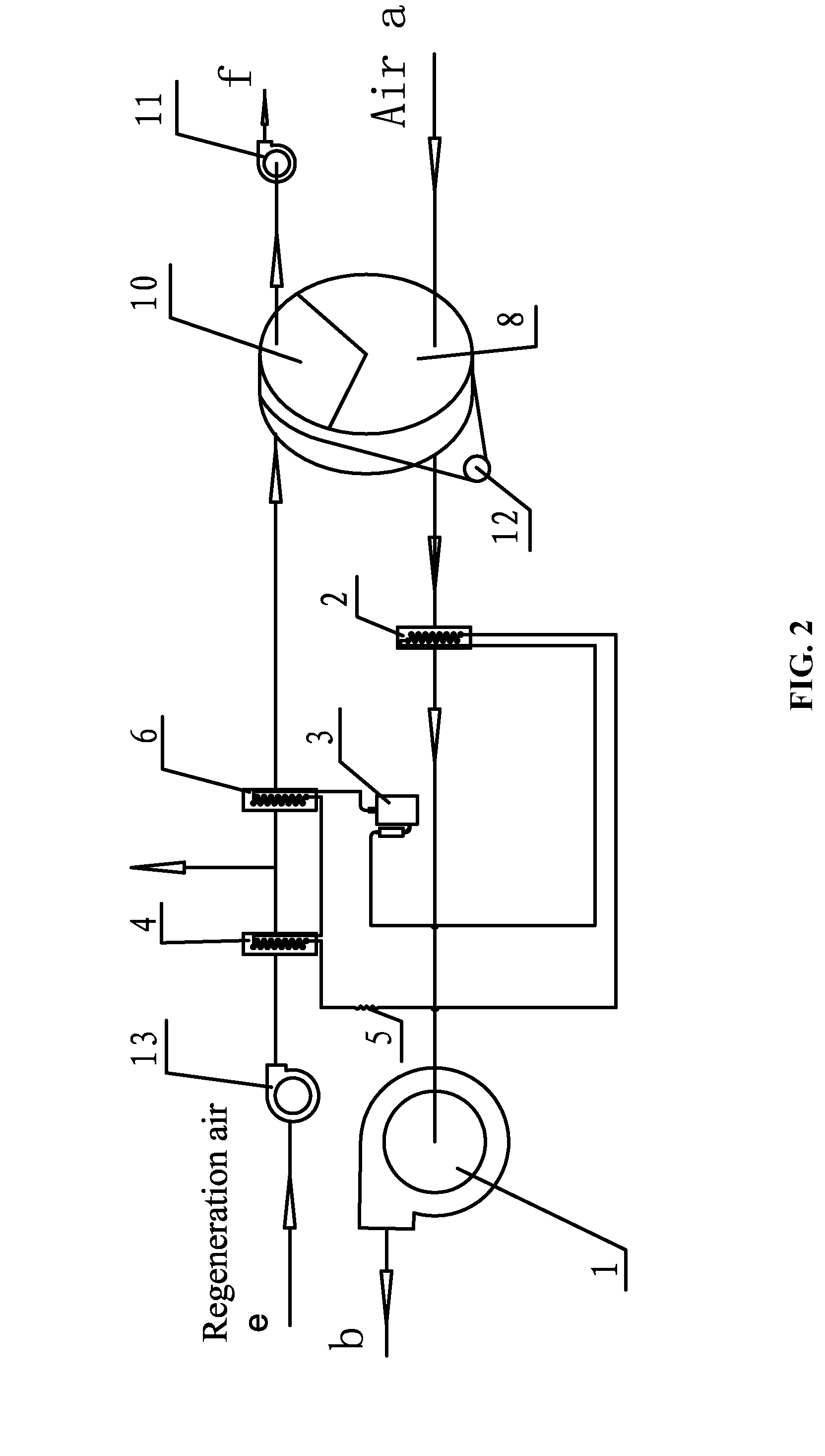
[0031]The invention provides a coupled air-conditioning device comprising a dehumidification system and a vapor compression-type refrigeration system which are connected through a pipeline.

[0032]As shown in FIG. 1, the vapor compression-type refrigeration system is a closed circuit comprising an evaporator 2, a compressor 3, a phase-change condensation heat exchanger 4, a refrigerant gas cooler 6 and an expansion valve 5. The phase-change condensation heat exchanger 4 has the structural form of a tube-fin type heat exchanger comprising a heat exchange tube and a fin piece.

[0033]The dehumidification system comprises a desiccant-wheel with a regeneration area 10 and a processing area 8, a processing air blower 1, a front regeneration air blower 13, a regeneration...


PUM


Abstract

A coupled air-conditioning device including a dehumidification system and a vapor compression-type refrigeration system which are connected through a pipeline. The vapor compression-type refrigeration system is a closed circuit including an evaporator, a compressor, a condenser and an expansion valve. The dehumidification system includes a desiccant-wheel with a regeneration area and a processing area, a processing air blower, a regeneration air blower and an electric motor driving the desiccant-wheel to rotate. The processing air blower and the regeneration air blower are provided with an exhaust port. The condenser includes a phase-change condensation heat exchanger and a refrigerant gas cooler. The refrigerant gas cooler operates to cool the overheated refrigerant discharged from the compressor into a saturated refrigerant in gas state, employing a structural form of a tube-fin heat exchanger comprising a heat exchange tube and a fin piece.

Description

CROSS-REFERENCE TO RELATED APPLICATIONS[0001]This application is a continuation-in-part of International Patent Application No. PCT / CN2012 / 000794 with an international filing date of Jun. 11, 2012, designating the United States, now pending, and further claims priority benefits to Chinese Patent Application No. 201110246146.0 filed Aug. 25, 2011, to Chinese Patent Application No. 201110359277.x filed Nov. 14, 2011, to Chinese Patent Application No. 201210048974.8 filed Feb. 29, 2012, and to Chinese Patent Application No. 201210133907.6 filed May 3, 2012. The contents of all of the aforementioned applications, including any intervening amendments thereto, are incorporated herein by reference. Inquiries from the public to applicants or assignees concerning this document or the related applications should be directed to: Matthias Scholl P. C., Attn.: Dr. Matthias Scholl Esq., 14781 Memorial Drive, Suite 1319, Houston, Tex. 77079.BACKGROUND OF THE INVENTION[0002]1. Field of the Inventio...

Claims


Application Information

Patent Timeline
Patent Type & Authority Applications(United States)
IPC IPC(8): F24F3/14
CPCB01D53/06B01D53/261F24F3/1423F24F3/147F24F5/0021Y02E60/14
Inventor MA, JUN
Owner MA JUN
Why Eureka
Try Eureka