
Method for removing impurities from flue gas condensate

Active Publication Date: 2014-06-19
PURETEQ
View PDF10 Cites 2 Cited by
  • Summary
  • Abstract
  • Description
  • Claims
  • Application Information

AI Technical Summary

Benefits of technology

The technical effect of this patent is to provide a simple and affordable way to effectively purify flue gas and its condensate.

Problems solved by technology

These compounds and components are toxic and highly undesirable.
Thus, it is desirable to have these impurities extracted from the flue gas as they are highly toxic to the environment.
Large plants may produce very large amounts of dirty flue gas condensate.
Thus, flue gas condensates are produced in enormous amounts.
However, this discharge of condensate presents a substantial risk to the environment and is therefore highly undesirable.
In conventionally used treatment methods, treatment is not sufficiently effective in purifying the flue gas to an environmentally safe level.
Especially, the amounts of heavy metals have been unsatisfactory until the present invention in conventionally treated (or untreated) flue gas condensates.
The methods and apparatuses described in the prior art are not suitable for handling condensed flue gas and reducing the amount of toxic metals.
Increased sulphate concentrations in wastewater are generally undesirable due to the corrosiveness of sulphate towards copper conduits and the risk of reductive formation of toxic and corrosive hydrogen sulphide (H2S).
However, one of the drawbacks of these two prior art methods is that the recycled liquid must pass through all the steps of the processes rendering the methods both cumbersome and material and energy-demanding.
However, the decomposition is slow (typically 1 to 2 days to complete decomposition) allowing for ample time to have CaS removed from the aqueous phase.

Method used


Image

  • Method for removing impurities from flue gas condensate
  • Method for removing impurities from flue gas condensate
  • Method for removing impurities from flue gas condensate

Examples


example 2

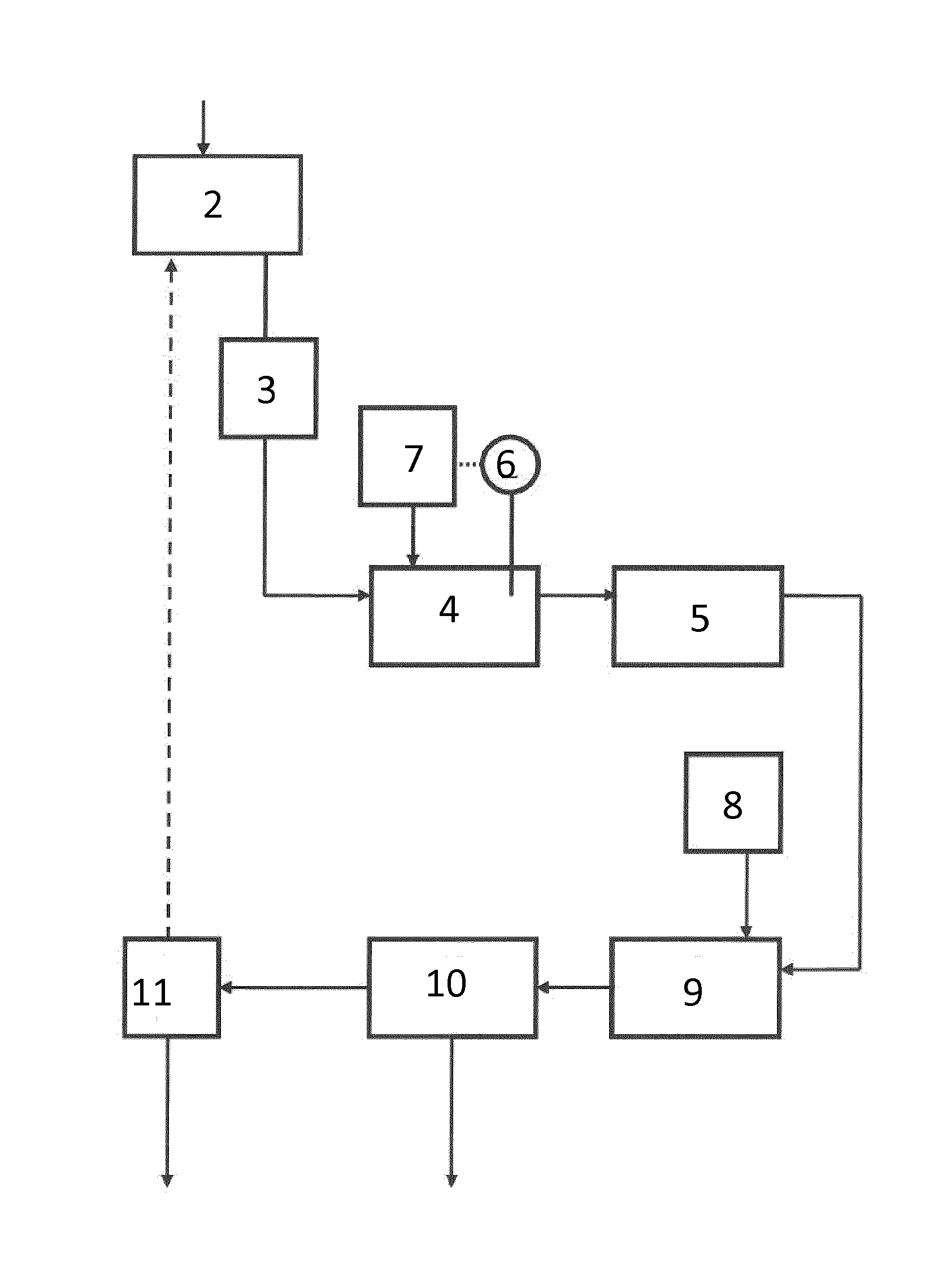
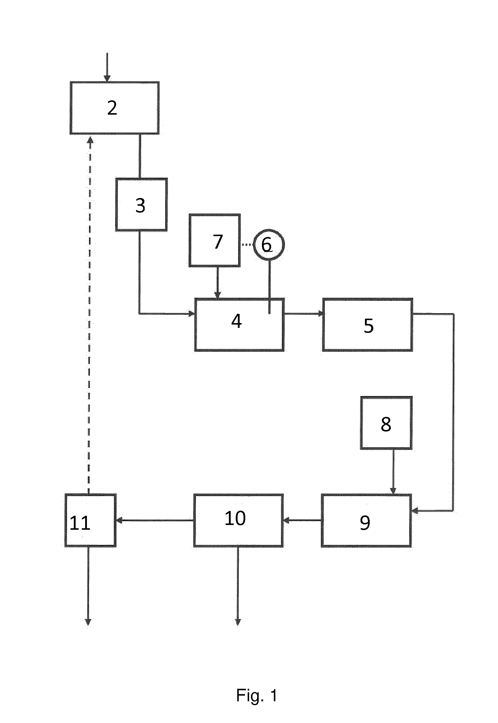
Wet Scrubbing of Flue Gas from Waste Incineration

[0183]Flue gas from waste incineration was treated in a system according to the invention. Approx. 40,000 normal m3 flue gases entered the scrubbing zone per hour. The scrubbing liquid was sprayed from nozzles within the scrubber into contact with the gas. To obtain a higher contact surface between liquid and gas, the scrubbing liquid was continuously recirculated in a loop circumventing the regeneration zone. The flow of this loop was approx. 330 m3 per hour.

[0184]The volume of liquid in the scrubbing zone was approx. 7 m3. Initially, this liquid was tap water, but as the process was running, the supernatant liquid of the first regeneration zone was recirculated and mixed with the tap water. This liquid had a circumneutral pH prior to contacting the acids (e.g. sulphur dioxide) of the flue gas.

[0185]A flow of 1,500 litres per hour of the scrubbing liquid was led into the first regeneration zone, first entering a heat exchanger for co...

example 3

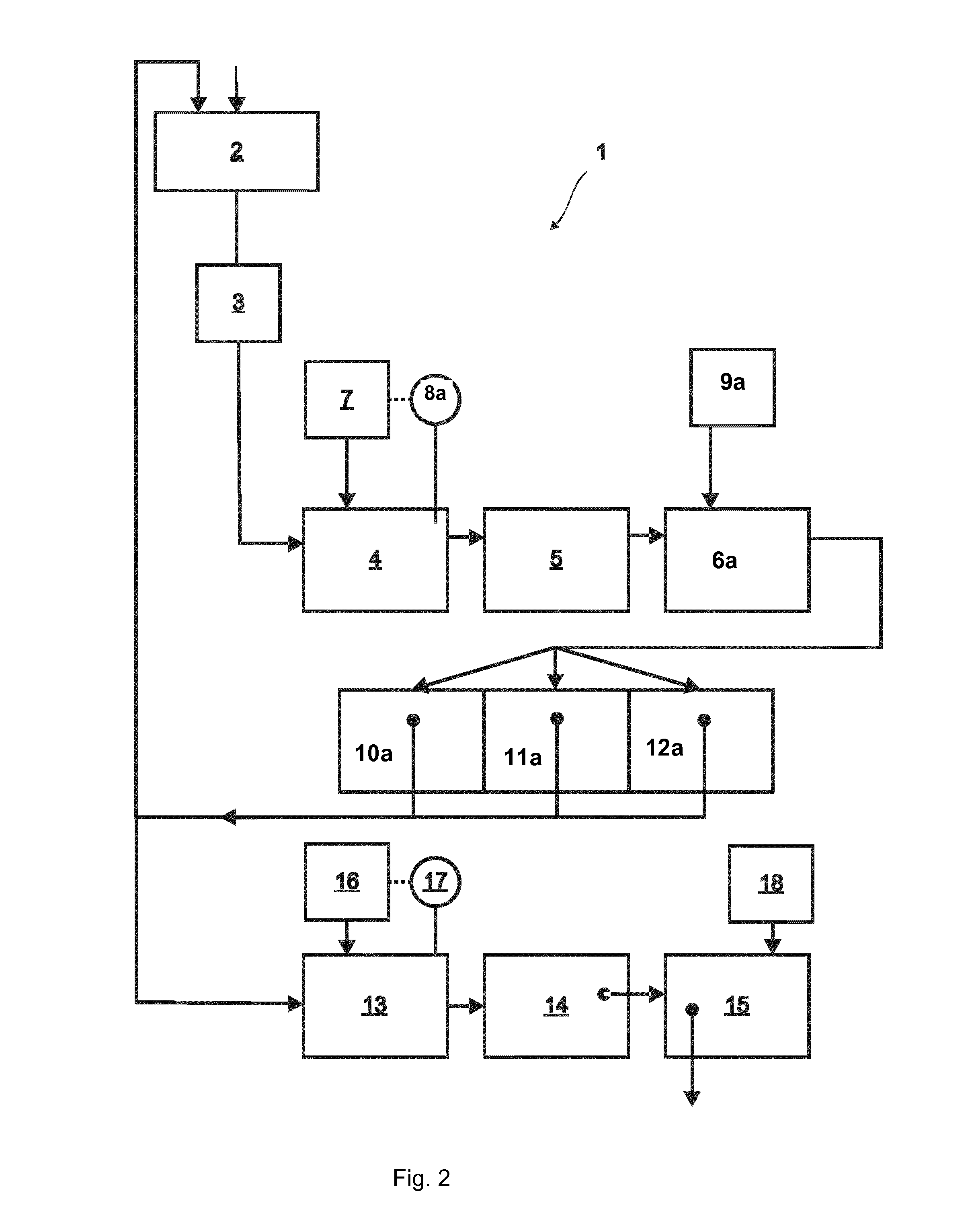
Purification of Scrubbing Liquid to Allow Discharge into the Sewer

[0188]Flue gas was treated as described in example 1, but part of the supernatant liquid was directed into a container for further purification to allow discharge into the sewer. The purpose of this treatment is to further reduce the content of dissolved sulphate to a level below the threshold limits for discharge into the sewer.

[0189]A flow of approx. 200 litres per hour of the supernatant emanating from the sedimentation tanks was directed into a second regeneration zone. The liquid was directed into a reactor, wherein Ca(OH)2 was added to the solution. A pH sensor measured the pH value of the mixture and triggered the influx of Ca(OH)2 up to a cut-off value of pH 11. The mixture was transferred to another container where it was aerated with CO2-enriched air using an air pump to lower the pH to pH 7. The resulting suspension containing precipitated calcium sulphate and calcium carbonate was then led into a sedimenta...

example 4

Illustrative Comparison of the Method of Present Invention and Conventional Method Using NaOH / HCl and Flocculation with Reference to FIG. 3

[0190]Flue gas is introduced into a first chamber G1 which initially contains water. In the comparison test, one part of the contents of G1 is treated according to examples 2 or 3 above. In the conventional process, flue gas is introduced into chamber G1 containing an aqueous solution (typically 400 L) which is continuously recycled back into G1 by spray nozzles to maximise the surface of contact by flue gas and water. Then, the gas is further passed on to G2, wherein the same process is repeated and the purified gas is then emitted into the atmosphere. Then, the aqueous phase resulting from this process (ca. 200 L) undergoes a water purification step consisting of regulation of the pH by addition of NaOH (ca. 6M) and / or HCl (ca. 6M) to afford a neutral pH, such that the pH of the solution is about 6-7. Then, the aqueous phase is transferred to a...


PUM

PropertyMeasurementUnit
Temperatureaaaaaaaaaa

Abstract

The present invention relates to a method for treating flue gas and / or condensates thereof suitable for removal of sulphur-containing compounds. The invention also relates to the purified flue gas and to a system for conducting the method according to the invention.

Description

TECHNICAL FIELD[0001]The present invention relates to a method and a system for removing impurities from flue gas and / or a condensate thereof. The invention further relates to a purified flue gas condensate obtainable by use of the inventive method. The invention also relates to a system for removing impurities from flue gas and / or a condensate thereof.BACKGROUND[0002]Various systems, methods and plants are available for cleaning flue gas. Flue gas contains various components including metals and compounds thereof. It is desirable to limit the concentration of these impurities from the flue gas prior to release of the flue gas into the atmosphere.[0003]Typically, flue gas contains toxic heavy metals, such as lead, cadmium, mercury, barium. Further, flue gas typically contains solid components such as fly ash. These compounds and components are toxic and highly undesirable.[0004]Thus, it is desirable to have these impurities extracted from the flue gas as they are highly toxic to the...

Claims


Application Information

Patent Timeline
IPC IPC(8): B01D53/73B01D5/00
CPCB01D53/002B01D53/74C02F1/66B01D2257/60B01D2258/0283C02F1/26C02F1/5245C02F2103/18C02F2209/02B01D5/009B01D53/73
Inventor SOGAARD, DENNIS
Owner PURETEQ
Features
  • Generate Ideas
  • Intellectual Property
  • Life Sciences
  • Materials
  • Tech Scout
  • Unparalleled Data Quality
  • Higher Quality Content
  • 60% Fewer Hallucinations
Learn More