Continuously height-adjustable intervertebral fusion implant

Inactive Publication Date: 2014-06-26
FACET LINK
View PDF15 Cites 39 Cited by
  • Summary
  • Abstract
  • Description
  • Claims
  • Application Information

AI Technical Summary

Benefits of technology

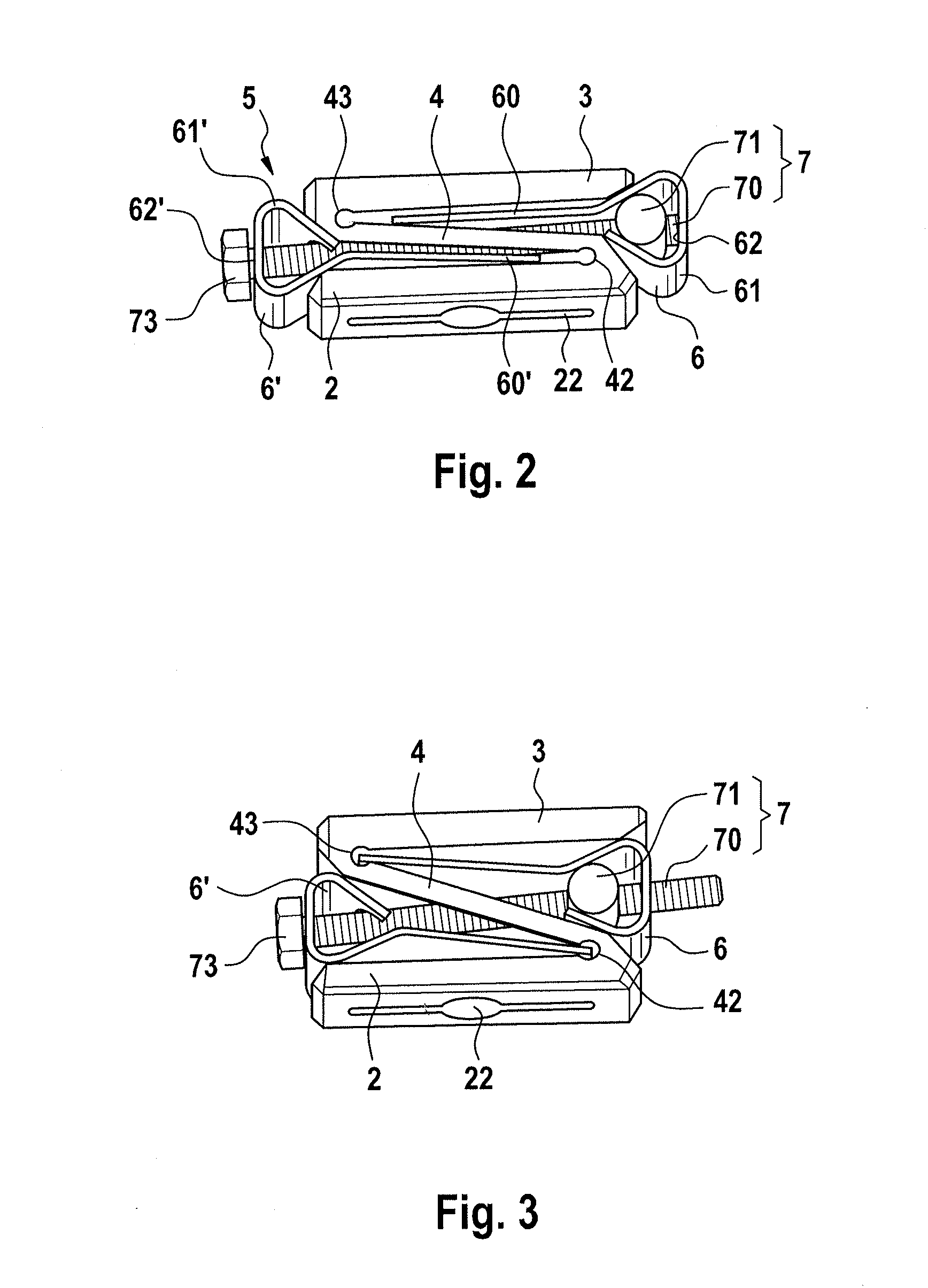
[0011]Provision is expediently made for two spreader clips situated opposite to one another. This affords the advantage of a larger and a symmetrical application of force from both sides. As a result of applying force from both sides, the risk of tilting between base piece and cover piece during the lifting movement is counteracted.
[0012]An expedient embodiment of the drive means is a contraction element. In this case, the spreader clip is pulled against a counterbearing, which can also be formed by a second spreader clip, and spreads open in the process. This enables a linear embodiment, which is particularly expedient in mechanical terms and which has significant advantages in respect of the compactness thereof in view of installation space aspects. A particularly expedient embodiment lies in the use of a screwing spindle as actuator for the drive means. It enables a high force transmission while at the same, time having low installation space requirements. Furthermore, the screwing spindle affords the advantage of an inherent self-retention, as a result of which there cannot be an inadvertent return of the achieved expansion. However, on the other hand, the screwing spindle allows the retraction of the expansion in a planned manner by actuation in the opposite direction.
[0013]The rocker is preferably configured in an integral embodiment with the hinges thereof. This reduces the number of parts and simplifies the

Problems solved by technology

The intervertebral disks of the vertebral column suffer degeneration as a result of wear or of pathological changes.
However, this advantage is obtained at the price of a very long access route through the abdominal cavity or thoracic cavity of the patient.
Although the latter affords the advantage of a short route, there is the danger of collision with or damage to the spinal cord.
Because of the small transverse incisions us

Method used


Image

  • Continuously height-adjustable intervertebral fusion implant
  • Continuously height-adjustable intervertebral fusion implant
  • Continuously height-adjustable intervertebral fusion implant

Examples


Embodiment Construction

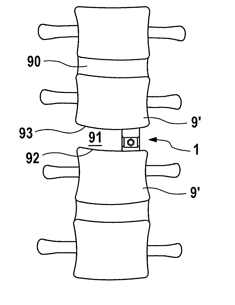
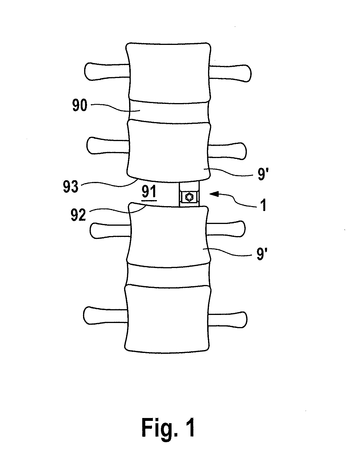
[0023]An intervertebral fusion implant, denoted by reference sign 1 in its entirety, is provided for implantation in an intervertebral space 91 between two immediately adjacent vertebral bodies 9, 9′. In a physiologically intact vertebral column, an intervertebral disk 90 is located in the intervertebral space between the vertebrae. This intervertebral disk may undergo degeneration as a result of disease or wear, with the result that it has to be at least partially resected. In order to achieve sufficient support of the intervertebral space 91, despite the loss of intervertebral disk material, and to thereby prevent collapse of the vertebral column, the intervertebral fusion implant 1 is inserted into the intervertebral space 91. It provides a supporting action and thus facilitates fusion of the two adjacent vertebrae 9, 9′ in a natural way through bone growth.

[0024]A first exemplary embodiment of an intervertebral fusion implant according to the invention, depicted in FIGS. 2 and 3...


PUM


Abstract

The invention relates to an intervertebral fusion implant for fusing two adjacent vertebrae, comprising a base piece and a cover piece and also a spreading means, wherein the base piece and the cover piece are connected by a rocker which is situated therebetween and externally coupled, and the spreading means is a spreader clip on the rocker and a drive device is provided for the spreader clip. The spreader clip is used to erect the rocker such that the implant expands in terms of height. As a result of the external coupling of the rocker, a large lifting travel is available. Furthermore, the spreader clip has a blocking effect in relation to an unwanted return as a result of the frictional forces thereof.

Description

REFERENCE TO RELATED APPLICATIONS[0001]This application is a nonprovisional of U.S. Provisional Application No. 61 / 738,267, filed Dec. 17, 2012, which claims priority to German Application No. 20 2012 011 959.1, filed Dec. 14, 2012, the entire contents of which are incorporated herein by reference.FIELD OF THE INVENTION[0002]The invention relates to an implant for fusing two adjacent vertebrae, comprising a base piece and a cover piece and also a spreading means.BACKGROUND OF THE INVENTION[0003]The intervertebral disks of the vertebral column suffer degeneration as a result of wear or of pathological changes. If conservative treatment by medication and / or physiotherapy is ineffective, surgical treatment is sometimes indicated. In this connection, it is known for a movable or immovable implant to be inserted into the intervertebral space containing the degenerated intervertebral disk. This implant takes over the support function of the degenerated intervertebral disk and to this exte...

Claims


Application Information

Patent Timeline
IPC IPC(8): A61F2/44
CPCA61F2/4455A61F2/442A61F2/447A61F2/4684A61F2002/2835A61F2002/30019A61F2002/30112A61F2002/30405A61F2002/30471A61F2002/30484A61F2002/30507A61F2002/3052A61F2002/30553A61F2002/30556A61F2002/30571A61F2002/30579A61F2002/30594A61F2002/30624A61F2002/30772A61F2002/30777A61F2002/30779A61F2002/448A61F2002/4635A61F2002/4638A61F2002/30014A61F2002/30593A61F2002/3037
Inventor DMUSCHEWSKY, KLAUS
Owner FACET LINK
Why Eureka
Try Eureka