
Power converter

a power converter and converter circuit technology, applied in the direction of battery/cell propulsion, engine-driven generator propulsion, transportation and packaging, etc., can solve problems such as interference between power converter circuits, and achieve the effect of reducing interference and increasing the current path

Active Publication Date: 2014-07-03
TOYOTA JIDOSHA KK +1
View PDF4 Cites 13 Cited by
  • Summary
  • Abstract
  • Description
  • Claims
  • Application Information

AI Technical Summary

Benefits of technology

The present invention is a power converter that prevents interference between different circuits caused by sudden voltage surges. This is achieved by adding extra slits to the bus bars that create longer current paths between the circuits, reducing the influence of surges on other circuits. In simple terms, this invention reduces interference between power converter circuits caused by surges.

Problems solved by technology

When a plurality of power converter circuits are combined to constitute a power converter and terminals of semiconductor modules of the power converter circuits are connected by a bus bar, interference may be caused between the power converter circuits by a surge voltage.

Method used


Image

  • Power converter
  • Power converter
  • Power converter

Examples


Embodiment Construction

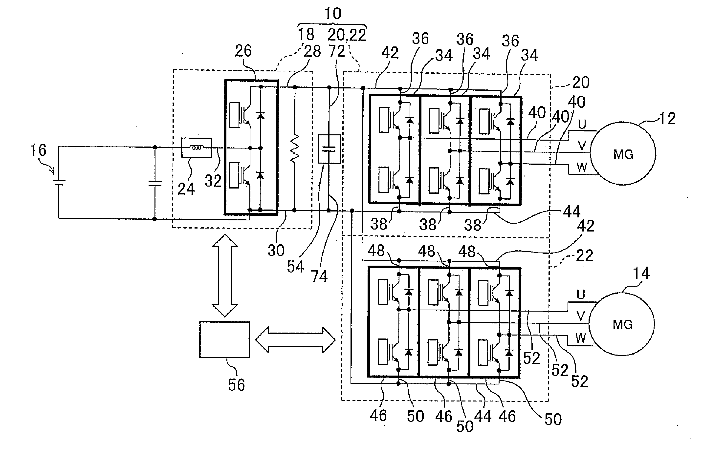
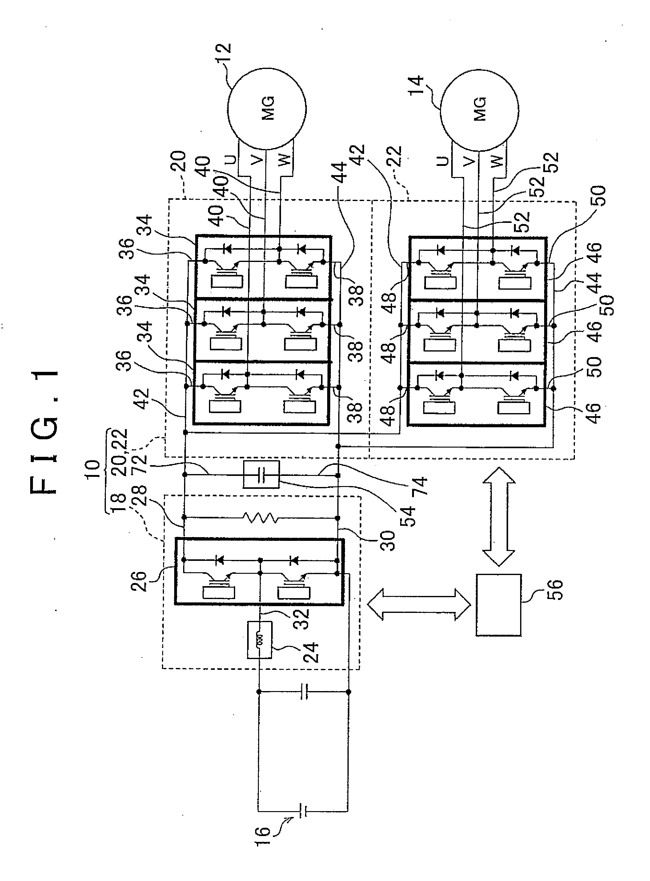
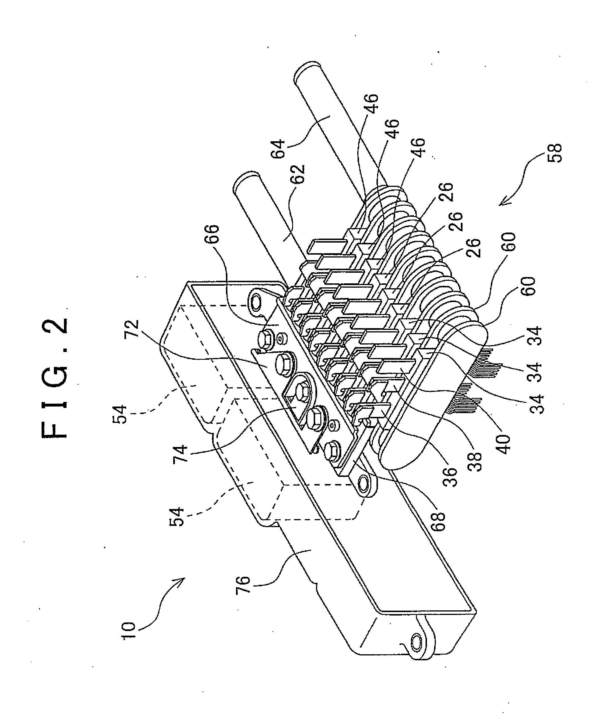
[0032]Description is hereinafter made of an embodiment of the present invention with reference to the drawings. FIG. 1 is a circuit configuration diagram that includes a power converter 10 of this embodiment. FIG. 1 is a diagram that illustrates the circuit configuration of a control system that drives first and second rotating electric machines 12 and 14 which function as driving motors of a hybrid vehicle. The two rotating electric machines 12 and 14 are rotatably driven by electric power from a secondary battery 16, and the secondary battery 16 is charged with electric power that is generated by the rotating electric machines 12 and 14. It is the power converter 10 that is used to drive the rotating electric machines 12 and 14 and charge the secondary battery 16. The power converter 10 includes a boost converter 18 that boosts the voltage of the secondary battery 16, and inverters 20 and 22 that convert the DC power from the secondary battery 16 into three-phase AC power and conv...


PUM


Abstract

A positive-electrode connecting plate (66) that connects positive-electrode terminals (28, 36, 48) of a plurality of power converter circuits is provided with slits (100, 102). The positive-electrode connecting plate has a positive-electrode bus bar portion (78) on which a first inverter corresponding region (94) that is connected to the positive-electrode terminal (36) of a first inverter as one of the power converter circuits via a positive-electrode connecting piece (80a), a second inverter corresponding region (96) that is connected to the positive-electrode terminal (48) of a second inverter as one of the power converter circuits via a positive-electrode connecting piece (80b) and a boost converter corresponding region (98) that is connected to the positive-electrode terminal (28) of a boost converter as one of the power converter circuits via a positive-electrode connecting piece (80c) are defined. The slits extend from an edge (82) of the positive-electrode bus bar portion along the boundaries between the regions.

Description

BACKGROUND OF THE INVENTION[0001]1. Field of the Invention[0002]The present invention relates to a power converter that converts AC power into DC power and converts DC power into AC power, and converts voltage.[0003]2. Description of Related Art[0004]A power converter circuit which converts DC power into AC power or converts AC power into DC, that is, an inverter is known. A power converter circuit which raises or lowers a DC voltage, that is, a boost converter is also known. A plurality of power converter circuits which change a characteristic of electric power (AC / DC, voltage, etc.) are sometimes integrally combined to constitute an power converter.[0005]One example of the use of a power converter is in a hybrid vehicle which is equipped with an internal combustion engine and an electric motor as driving sources. A three-phase AC synchronous motor is sometimes used as the electric motor for a hybrid vehicle. The electric motor functions also as a power generator to generate electr...

Claims


Application Information

Patent Timeline
Patent Type & Authority Applications(United States)
IPC IPC(8): H05K7/02B60L50/15H02M1/00
CPCH05K7/023H02M7/003B60L15/007B60L2210/40B60L50/61B60L50/51Y02T10/62Y02T10/64Y02T10/70Y02T10/72H05K7/14329Y02T10/7072H05K7/1432
Inventor IWATA, KUNIHIROOKAMURA, MAKOTO
Owner TOYOTA JIDOSHA KK
Learn More