Spectral grating-based differential phase contrast system for medical radiographic imaging

a technology of differential phase contrast and radiographic imaging, applied in the field of digital xray imaging methods/systems, can solve problems such as poor contrast compared with bone images

a technology of differential phase contrast and radiographic imaging, applied in the field of digital xray imaging methods/systems, can solve problems such as poor contrast compared with bone images

US20140185746A1Active Publication Date: 2014-07-03CARESTREAM HEALTH INC

Image

  • Spectral grating-based differential phase contrast system for medical radiographic imaging
  • Spectral grating-based differential phase contrast system for medical radiographic imaging
  • Spectral grating-based differential phase contrast system for medical radiographic imaging

Examples


Embodiment Construction

[0047]The following is a detailed description of exemplary embodiments according to the application, reference being made to the drawings in which the same reference numerals identify the same elements of structure in each of the several figures.

[0048]To be useful for clinical imaging, the phase contrast imaging systems must meet various requirements including: (i) use of a standard broadband x-ray source; (ii) a large field of view (FOV) of many centimeters (e.g., 24 cm×30 cm for a typical mammography system); (iii) a reasonably compact design comparable to current radiographic imaging systems (e.g., the source-to-detector distance is about 65 cm for a typical mammography system); and / or (iv) a reasonable exposure time and dose (e.g., the mean exposure for a typical mammography system is about 5 mR).

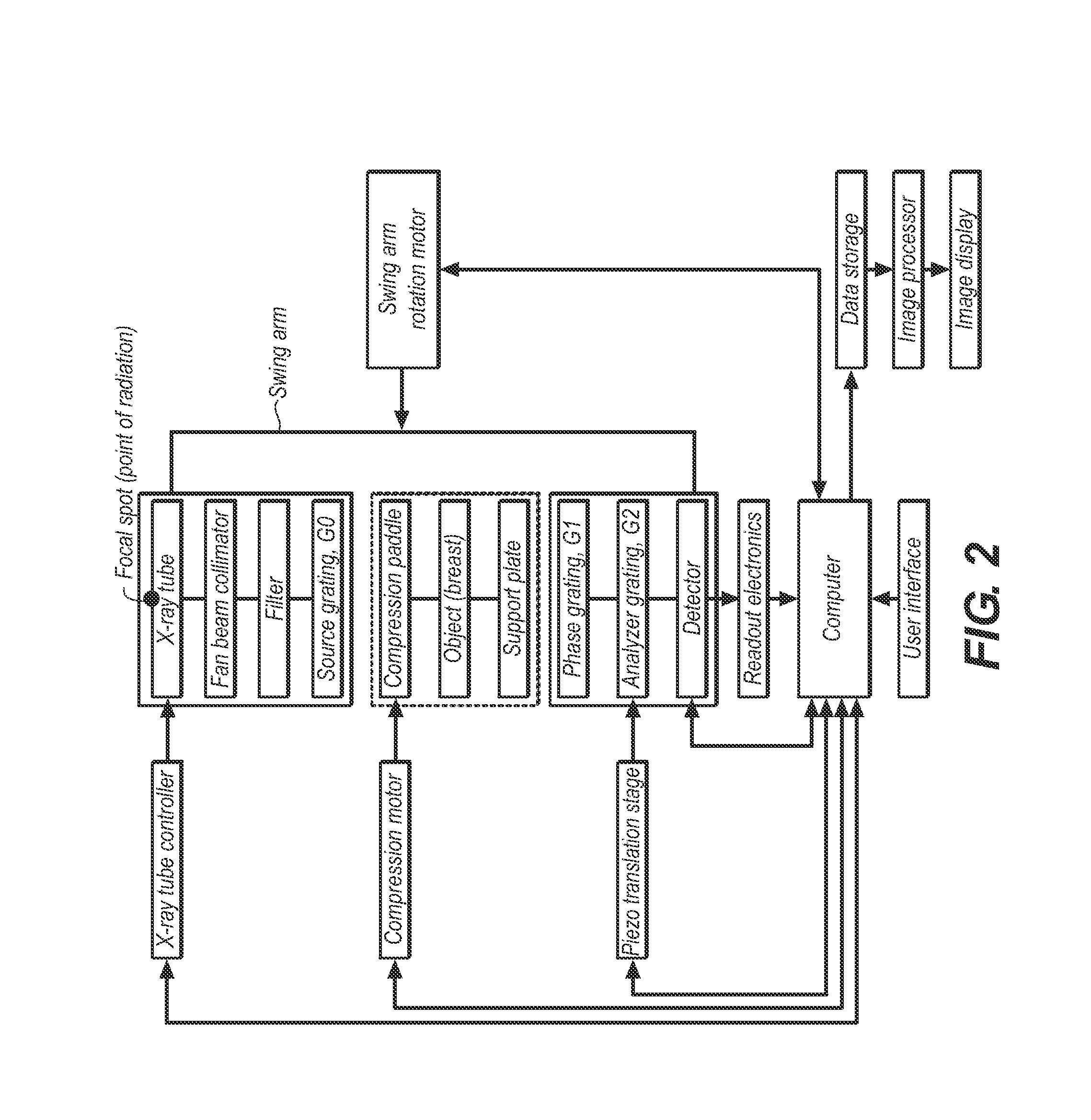
[0049]1. System Configuration

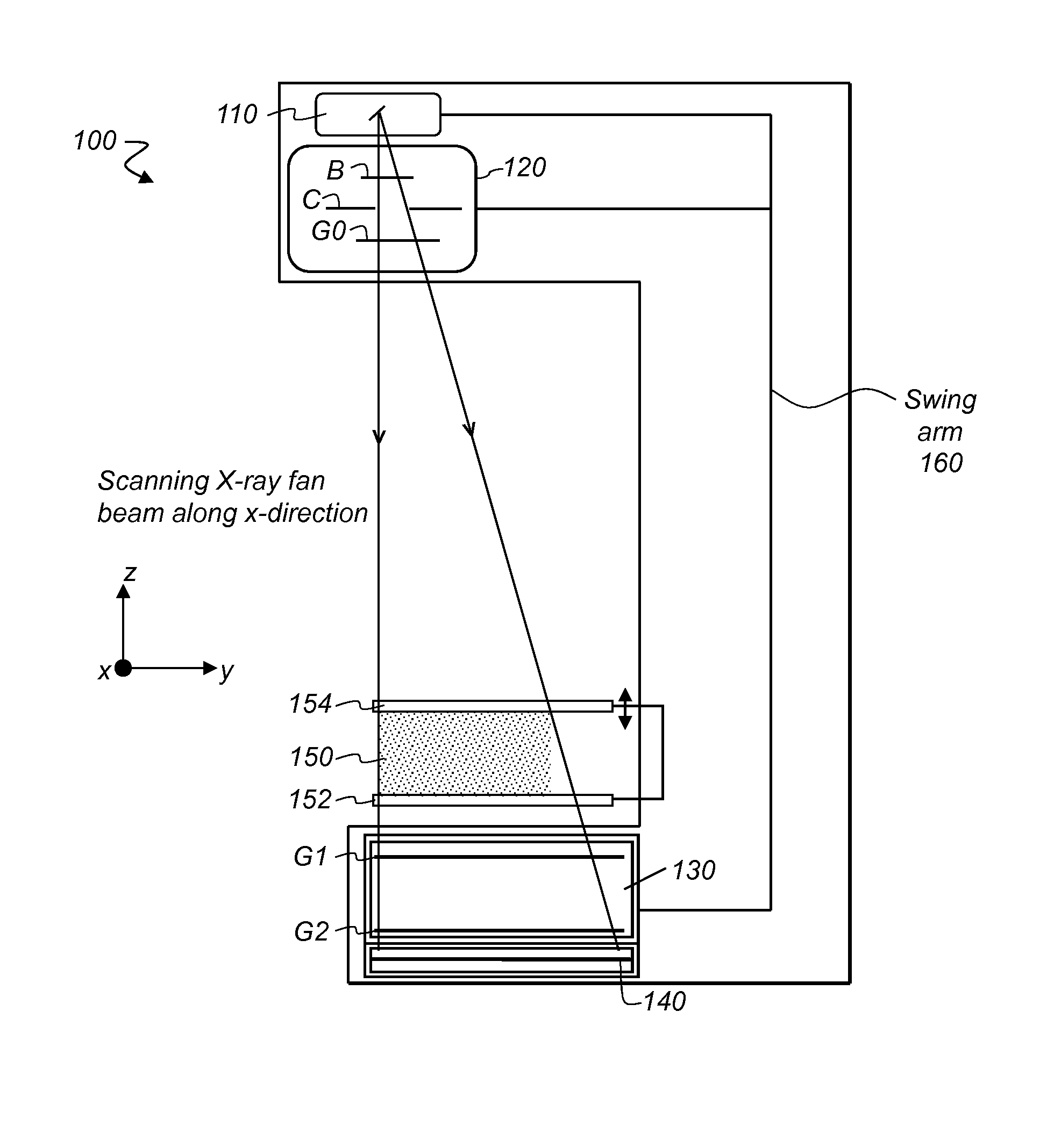
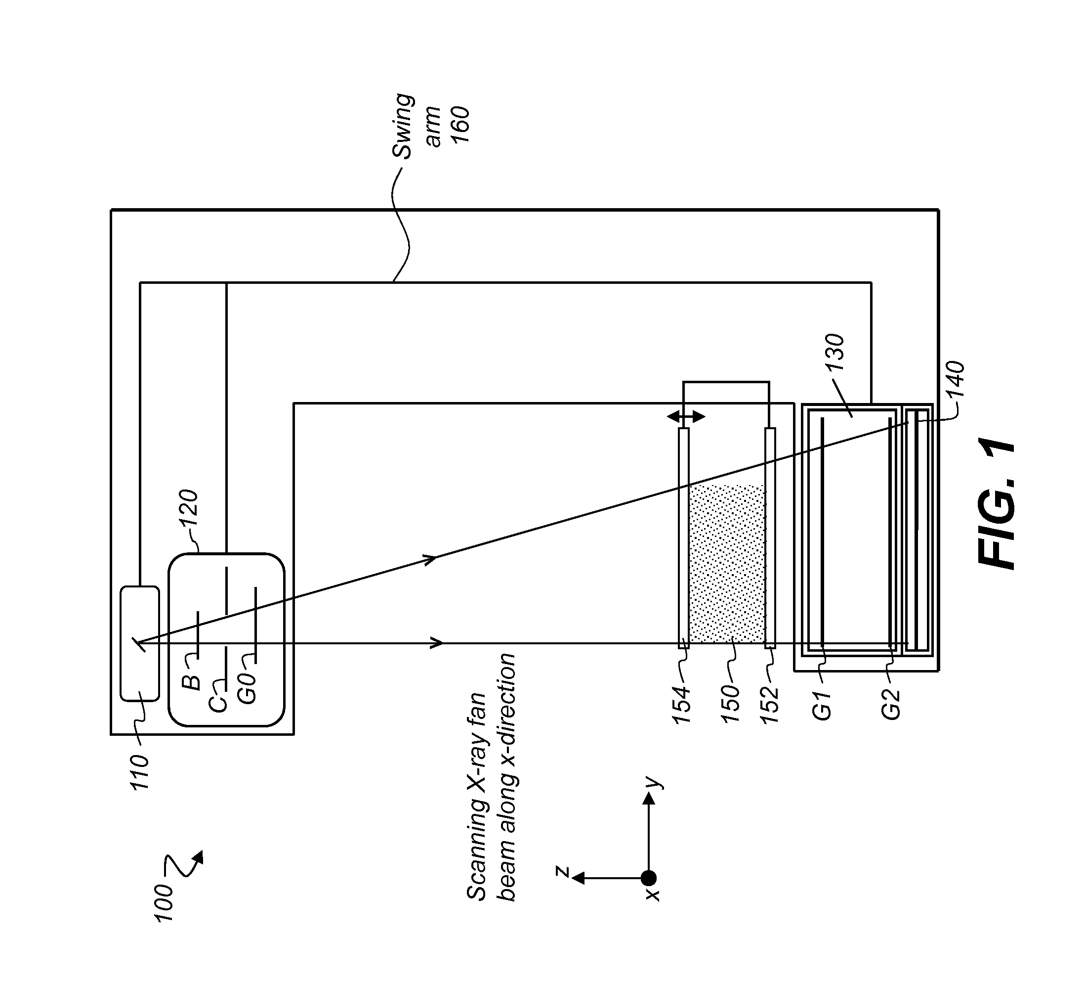
[0050]FIG. 1 is a diagram that shows an exemplary embodiment of a slot-scanning phase-contrast imaging system in accordance with the application. As shown i...


PUM


Abstract

Embodiments of methods and apparatus are disclosed for obtaining a phase-contrast digital radiographic imaging system and methods for same that can include an x-ray source for radiographic imaging; a beam shaping assembly including a collimator and a source grating, an x-ray grating interferometer including a phase grating, and an analyzer grating; and an x-ray detector, where a single arrangement of the beam shaping assembly, the x-ray grating interferometer and a position of the detector is configured to provide spectral information (e.g. at least two images obtained at different relative beam energies).

Description

FIELD OF THE INVENTION[0001]The application generally relates to digital x-ray imaging methods / system, and more specifically, to methods and / or systems for acquiring multiple image information of an object (e.g., medical radiographic imaging) using a grating-based differential phase contrast imaging technique.BACKGROUND OF THE INVENTION[0002]Conventional medical x-ray imaging devices are based on the attenuation through photoelectric absorption of the x-rays penetrating the object to be imaged. However, for soft tissues including vessels, cartilages, lungs, and breast tissues with little absorption, this provides poor contrast compared with bone images. This problem of low contrast in soft tissues can be addressed with phase contrast imaging (PCI) techniques.[0003]The principle of PCI is based on the wave nature of x-rays, where refraction and diffraction properties need to be considered. As an electromagnetic wave, the x-ray is usually characterized by its frequency, amplitude, and...

Claims


Application Information

Patent Timeline
03 Jul 2014
Publication
US20140185746A1
IPC
A61B6/00
CPC
A61B6/484; A61B6/06; A61B6/4035; G21K1/06; A61B6/482; A61B6/502; A61B6/4241; G21K2207/005
Inventors
BATURIN, PAVLO; SHAFER, MARK E.