Method of Timing Laser Beam Pulses to Regulate Extreme Ultraviolet Light Dosing

a laser beam and pulse technology, applied in the field of photolithography, can solve the problems of time-consuming and laborious, variability in output, and difficulty in achieving maximum euv output light across bursts over tim

Active Publication Date: 2014-07-10
ASML NETHERLANDS BV
View PDF13 Cites 14 Cited by
  • Summary
  • Abstract
  • Description
  • Claims
  • Application Information

AI Technical Summary

Benefits of technology

[0011]In one embodiment is provided a method of regulating a dose of energy produced during stroboscopic firing of an EUV light source configured to generate an energy dose target within one or more packet comprising: (a) setting by a laser controller a dose servo value for a current packet; (b) timing by the laser controller a trigger to pulse a laser beam to irradiate a droplet during the current packet; (c) sensing by a sensor EUV energy generated by irradiation of the droplet; (d) accumulating by the laser controller the sensed EUV energy with EUV energy generated by irradiation of one or more preceding droplet during the current packet; (e) repeating steps (b), (c), and (d) when the accumulated EUV energy within the current packet is less than an adjusted dose target based on the energy dose target and an accumulated dose error; and (f) mistiming by the laser controller the trigger to pulse the laser beam to not irradiate another droplet during the current packet.
[0012]In another embodiment is the method further comprising: (g) calculating by the laser controller a dose error for the current packet; (h) accumulating by the laser controller the dose error for the current packet with a dose error for one or more preceding packet; (i) calculating by the laser controller a new adjusted dose target for a next packet based on the energy dose target and the accumulated dose error; and (j) calculating by the laser controller a new dose servo value for the next packet.
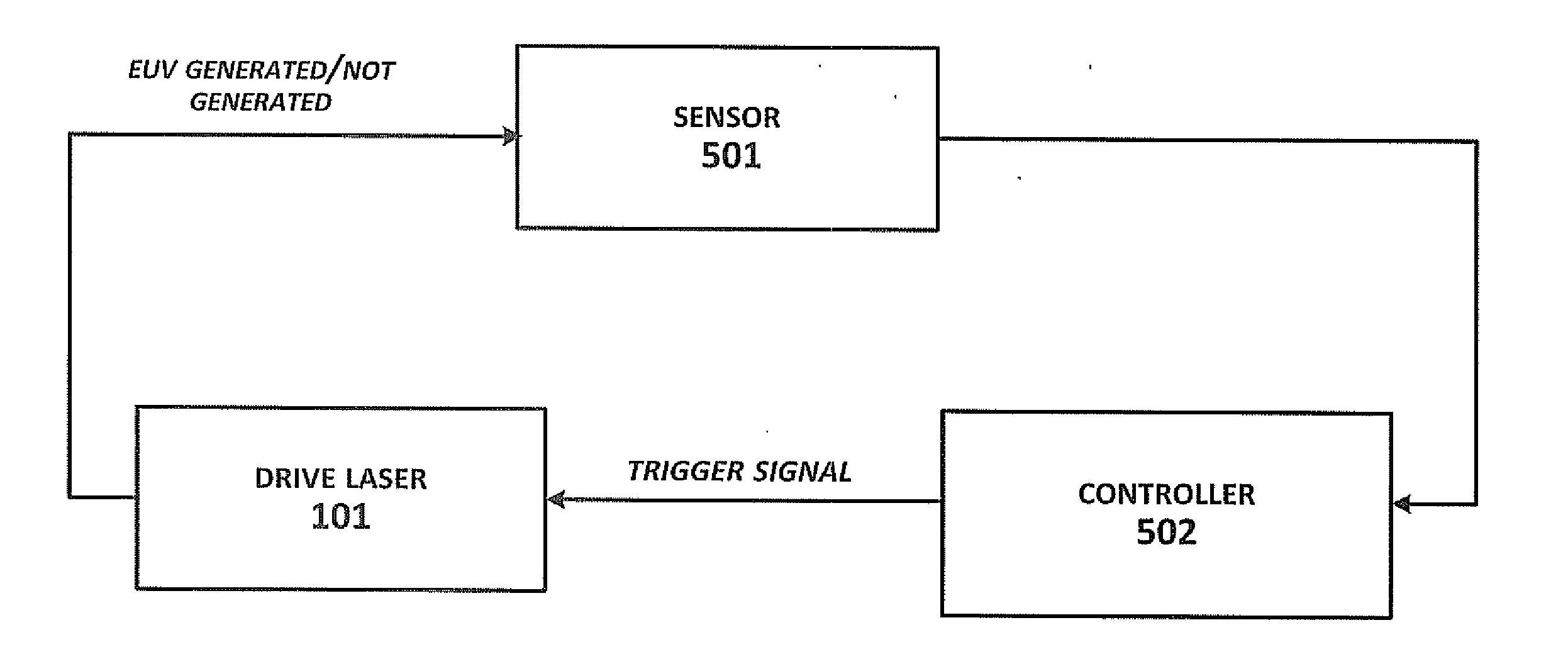
[0013]In still another embodiment a system for regulating a dose of energy produced during stroboscopic burst-firing of an EUV light source configured to generate an energy dose target within one or more packet comprising: a drive laser configured to pulse a laser beam when a trigger is received; a sensor configured to sense EUV energy generated by irradiation of a droplet; and a controller configured to: (a) set a dose servo value for a current packet; (b) time the trigger to pulse the laser beam to irradiate a droplet during the current packet; (c) accumulate sensed EUV energy generated by irradiation of the droplet with EUV energy generated by irradiation of one or more preceding droplet during the current packet; (d) repeat steps (b) and (c) when the accumulated EUV energy within the current packet is less than an adjusted dose target based on the energy dose target and an accumulated dose error; and (e) mistime the trigger to pulse the laser beam to not irradiate another droplet during the current packet.
[0014]In yet another embodiment is the system wherein the controller is further configured to: (f) calculate a dose error for the current packet; (g) accumulate the dose error for the current packet with a dose error for one or more preceding packet; (h) calculate a new adjusted dose target for a next packet based on the energy dose target and the accumulated dose error; and (i) calculate a new dose servo value for the next packet.
[0015]A method of regulating a dose of energy produced during continuous burst mode of an EUV light source comprising: (a) beginning a burst having a predetermined energy dose target; (b) timing by the laser controller a trigger to pulse a laser beam to irradiate a droplet during the burst; (c) sensing EUV energy generated by the droplet; (d) calculating by the laser controller a current dose error for the droplet based on the sensed EUV energy and the energy dose target; (e) accumulating by the laser controller a burst error based on the current dose error and a running burst error calculated for one or more preceding droplet during the burst; (e) repeating steps (b)-(e) for a next droplet when the burst is not finished and the accumulated burst error does not meet or exceed a threshold burst error; (f) mistiming by the laser controller the trigger to pulse the laser beam to not irradiate the next droplet when the burst is not finished and the accumulated burst error meets or exceeds the threshold burst error; and (g) repeating steps (c)-(g) until the burst is finished.
[0016]A system for regulating a dose of energy produced during continuous burst firing of an EUV light source configured to generate an energy dose target comprising: a drive laser configured to pulse a laser beam when a trigger is received; a sensor configured to sense EUV energy generated by irradiation of a droplet; and a controller configure to: (a) time the trigger to pulse a laser beam to irradiate a droplet during the burst; (b) calculate a current dose error for the droplet based on the sensed EUV energy and the energy dose target; (c) accumulate a burst error based on the current dose error and a running burst error calculated for one or more preceding droplet during the burst; (d) repeat steps (a)-(c) for a next droplet when the burst is not finished and the accumulated burst error does not meet or exceed a threshold burst error; (e) mistime the trigger to pulse the laser beam to not irradiate the next droplet when the burst is not finished and the accumulated burst error meets or exceeds the threshold burst error; and (f) repeat steps (b)-(e) until the burst is finished.

Problems solved by technology

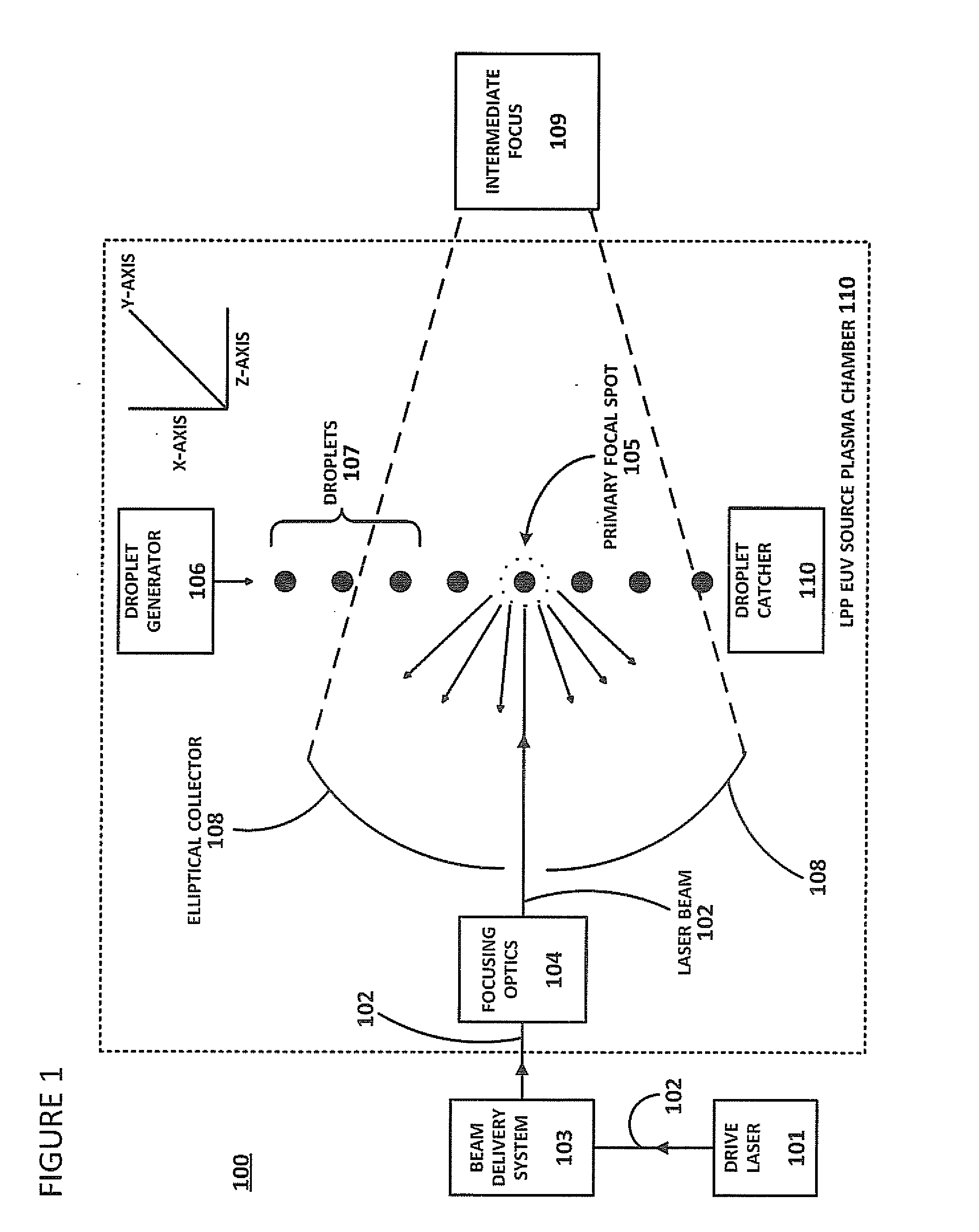
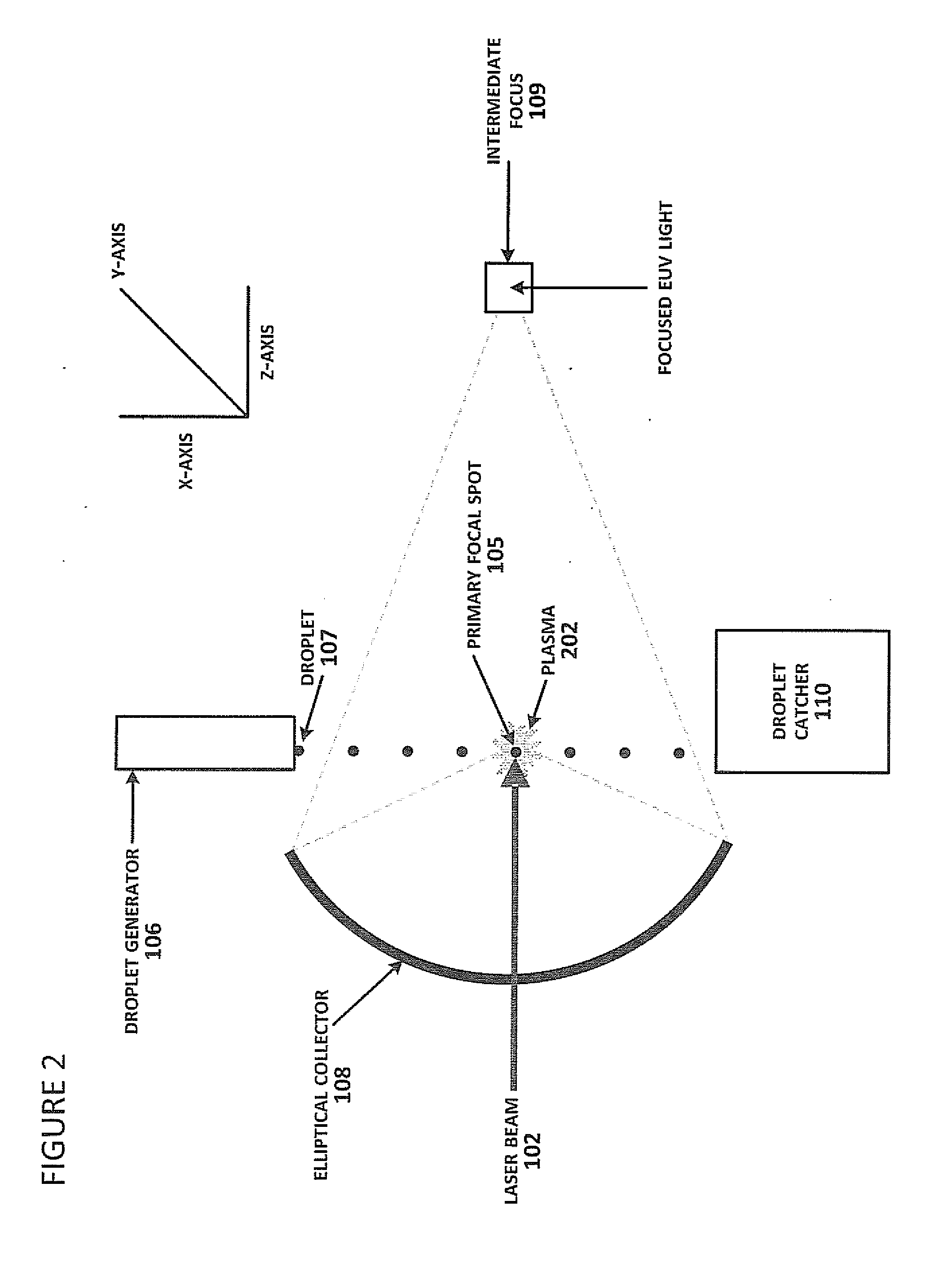
Delivering this target material and the laser beam simultaneously to a desired irradiation site (e.g., a primary focal spot) within an LPP EUV source plasma chamber for plasma initiation presents certain timing and control challenges.
In reality, however, achieving maximal EUV output light across bursts over time is very difficult because energy generated by irradiation of one droplet varies randomly from energy generated by irradiation of another droplet.
This variability in output is a problem for downstream utilization of the EUV light.
For example, if variable EUV light is used downstream in a lithography scanner, wafers can be non-uniformly processed, with resultant diminution of quality control of dies cut from the wafers.

Method used


Image

  • Method of Timing Laser Beam Pulses to Regulate Extreme Ultraviolet Light Dosing
  • Method of Timing Laser Beam Pulses to Regulate Extreme Ultraviolet Light Dosing
  • Method of Timing Laser Beam Pulses to Regulate Extreme Ultraviolet Light Dosing

Examples


Embodiment Construction

[0027]As discussed above, energy (light) output by an EUV system can be used downstream in a number of applications, e.g., semiconductor lithography. In a typical scenario, EUV output might be passed to a lithography scanner in stroboscopic bursts to irradiate photoresist on successive wafers. In laser systems with no master oscillator (i.e., “NOMO” systems), such stroboscopic bursts of energy are achieved by controlling RF pump power to switch a laser between “on” and “off” states. Thus, the amount of energy passed for downstream dosing is controlled by this RF power pumping.

[0028]MOPA laser systems (i.e., systems with a master oscillator and power amplifier, including those with a pre-pulse configuration, “MOPA+PP systems”) are capable of generating higher power output from a pulsed laser source than are NOMO systems, and are therefore preferable for some downstream applications. Downstream dosing in MOPA systems is not, however, as easily controlled as in NOMO systems because of ...


PUM


Abstract

Described herein are embodiments of a method to control energy dose output from a laser-produced plasma extreme ultraviolet light system by adjusting timing of fired laser beam pulses. During stroboscopic firing, pulses are timed to lase droplets until a dose target of EUV has been achieved. Once accumulated EUV reaches the dose target, pulses are timed so as to not lase droplets during the remainder of the packet, and thereby prevent additional EUV light generation during those portions of the packet. In a continuous burst mode, pulses are timed to irradiate droplets until accumulated burst error meets or exceeds a threshold burst error. If accumulated burst error meets or exceeds the threshold burst error, a next pulse is timed to not irradiate a next droplet. Thus, the embodiments described herein manipulate pulse timing to obtain a constant desired dose target that can more precisely match downstream dosing requirements.

Description

CROSS-REFERENCE TO RELATED APPLICATIONS[0001]This application is related to U.S. patent application Ser. No. ______ (Dkt. No. PA1184US), entitled “A Method of Timing Laser Beam Pukes to Regulate Extreme Ultraviolet Light Dosing,” filed on even date herewith.BACKGROUND OF THE INVENTION[0002]1. Field of the Invention[0003]The present invention relates generally to laser technology for photolithography, and more particularly to EUV dose control during laser firing.[0004]2. Description of the Prior Art[0005]The semiconductor industry continues to develop lithographic technologies which are able to print ever-smaller integrated circuit dimensions. Extreme ultraviolet (“EUV”) light (also sometimes referred to as soft x-rays) is generally defined to be electromagnetic radiation having wavelengths of between 10 and 110 nm. EUV lithography is generally considered to include EUV light at wavelengths in the range of 10-14 nm, and is used to produce extremely small features (e.g., sub-32 nm fea...

Claims


Application Information

Patent Timeline
Patent Type & Authority Applications(United States)
IPC IPC(8): G21K5/00
CPCG21K5/00H05G2/003H05G2/008
Inventor CROUCH, JAMESJACQUES, ROBERTGRAHAM, MATTHEW R.LIU, ANDREW
Owner ASML NETHERLANDS BV
Why Eureka
Try Eureka