Real time control of high intensity focused ultrasound using magnetic resonance imaging

a high-intensity, focused ultrasound technology, applied in the direction of instruments, nmr measurement, therapy, etc., can solve the problems of long diagnostic image calculation, high cost, and inability to achieve real-time feedback loops, so as to accelerate processing and increase the rate

Active Publication Date: 2014-07-10
PROFOUND MEDICAL
View PDF15 Cites 8 Cited by
  • Summary
  • Abstract
  • Description
  • Claims
  • Application Information

AI Technical Summary

Benefits of technology

[0042]In another embodiment execution of the instructions causes the processor to broadcast the magnetic resonance data to the sonication control module. This embodiment may be particularly advantageous because the sonication control module is using the broadcast or raw magnetic resonance data. This may bypass the imaging function of the magnetic resonance imaging system completely. In some embodiments the sonication control module may strip away useless data which may accelerate the processing.
[0043]In another embodiment the sonication control module is configured to control the high-intensity focused ultrasound system without generating images from the magnetic resonance data. This may have the benefit because it may increase the rate at which the sonication control module functions.

Problems solved by technology

Customized real-time reconstruction hardware and software has been used in Magnetic Resonance Imaging (MRI) bolus tracking and in experimental fast reconstruction methods, but no attempts have been made to create sustainable, non-diagnostic feedback loops entirely in the real-time domain.
Diagnostic image calculations are typically lengthy operations and much effort is spent to produce visually meaningful image data, at the expense of reconstruction time and complexity.
Diagnostic image calculations are typically carried out in a non-real-time environment due to the complexity and easy expandability.
The non-real-time operating systems cause large jitter and performance variability in image throughput.
As a result, the feedback loop optimization remains conservative due to too many unknown variables in the loop path.

Method used


Image

  • Real time control of high intensity focused ultrasound using magnetic resonance imaging
  • Real time control of high intensity focused ultrasound using magnetic resonance imaging
  • Real time control of high intensity focused ultrasound using magnetic resonance imaging

Examples


Embodiment Construction

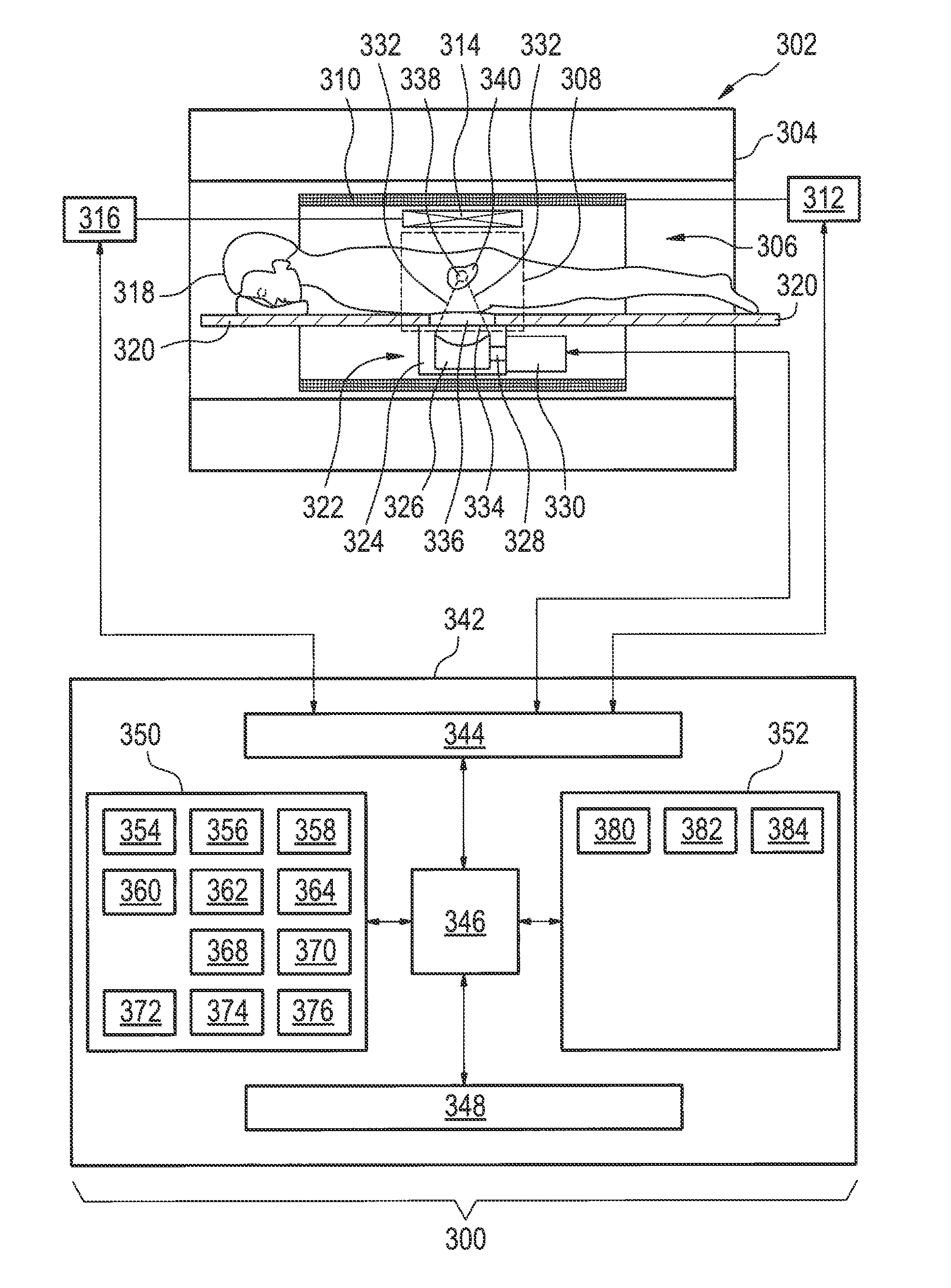
[0052]Like numbered elements in these figures are either equivalent elements or perform the same function. Elements which have been discussed previously will not necessarily be discussed in later figures if the function is equivalent.

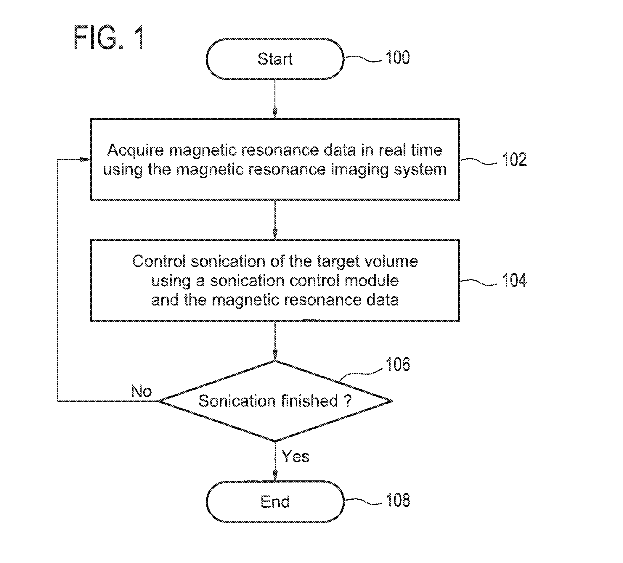
[0053]FIG. 1 shows a flow diagram which illustrates a method according to an embodiment of the invention. The method starts in step 100. Next in step 102 magnetic resonance data is acquired in real time using the magnetic resonance imaging system. Next in step 104 the sonication of the target volume is controlled using a sonication control module which uses the magnetic resonance data that was acquired in real time as input. Box 106 is a decision box. If the sonication is not finished then the method returns back to step 102. Then steps 102 and 104 are repeated until the sonication is finished. After the sonication is finished the method ends in step 108.

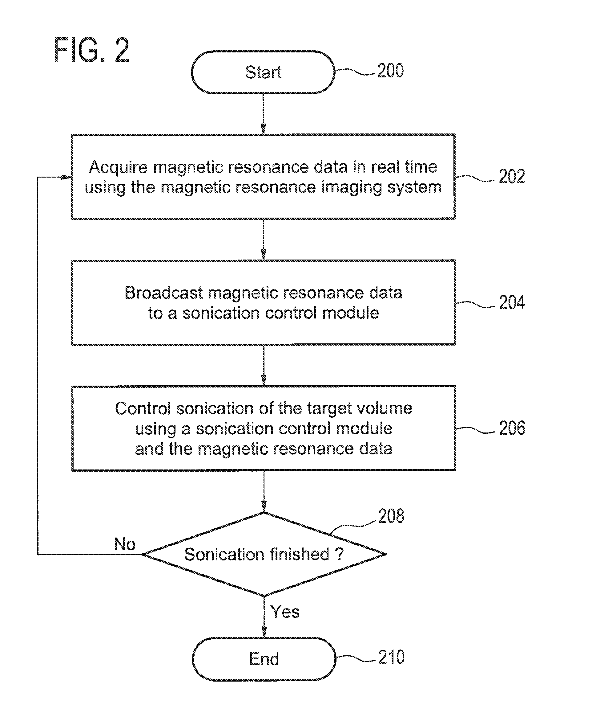
[0054]FIG. 2 shows a flow diagram which illustrates a further method according to an embodiment of t...


PUM


Abstract

A medical apparatus (300, 400, 500) comprises a high intensity focused ultrasound system (322) configured for for sonicating a target volume (340) of a subject (318). The medical apparatus further comprises a magnetic resonance imaging system (302) for acquiring magnetic resonance data (356, 358, 360, 368, 374) from an imaging zone (308). The treatment volume is within the imaging zone. The medical apparatus further comprises a memory (352) containing machine executable,a control module (382, 402) for controlling the sonication of the target volume using the magnetic resonance data as a control parameter, and a processor (346). Execution of the instructions causes the processor to repeatedly acquire (102, 202) magnetic resonance data in real time using the magnetic resonance imaging system and control (104, 206) sonication of the target volume by the high intensity focused ultra-sound system in real time using the sonication control module and the magnetic resonance data.

Description

TECHNICAL FIELD[0001]The invention relates to high intensity focused ultrasound, in particular the invention relates to magnetic resonance image guided high intensity focused ultrasound.BACKGROUND OF THE INVENTION[0002]In recent years, magnetic resonance thermometry has been coupled with various means of heating or cooling tissue for therapy. Measuring the effect of the tissue heating or cooling allows the guiding of the therapy and also the ability to assess the effect of a therapeutic treatment on a subject.[0003]In high-intensity focused ultrasound (HIFU) therapy, reliable real-time temperature monitoring using, e.g., Magnetic Resonance Imaging (MRI) is necessary to ensure a sufficient thermal necrosis to the target while avoiding excessive heating and damage of surrounding healthy tissues. To achieve sufficient temporal and spatial resolution, fast imaging is required preferably with a high spatial resolution while maintaining a sufficient SNR for reconstruction of reliable temp...

Claims


Application Information

Patent Timeline
Patent Type & Authority Applications(United States)
IPC IPC(8): G01R33/28A61B8/08G01R33/48A61B5/055A61B5/00A61B17/32
CPCG01R33/285A61B17/320016A61B17/320068G01R33/4818A61B5/4836A61B8/485G01R33/4814A61B5/055A61B8/565A61N7/02A61B2090/374A61B2017/320069A61B5/0036
Inventor VAHALA, ERKKI TAPANI
Owner PROFOUND MEDICAL
Why Eureka
Try Eureka