Controller and power source for implantable blood pump

a technology of controller and power source, which is applied in the field of implantable medical devices, can solve the problems of relative short surgery time and quick recovery, and achieve the effect of reducing efficiency

Active Publication Date: 2014-07-10
HEARTWARE INC
View PDF1 Cites 65 Cited by
  • Summary
  • Abstract
  • Description
  • Claims
  • Application Information

AI Technical Summary

Benefits of technology

[0015]In one embodiment, a control system for driving an implantable blood pump includes a first housing including electronic components configured to drive the pump and a second housing including a battery. The first housing includes a first latch member extending from the first housing on a first side of the first housing and first and second recesses on a second side of the first housing. The second housing includes a third recess on a first side of the second housing and second and third latch members extending from the second housing on a second side of the second housing. When the first side of the first housing is aligned with the first side of the second housing, the first latch member aligns with the third recess, the second latch member aligns with the first recess, and the third latch member aligns with the second recess. The second and third latch members may each include bottom connected to the second housing and a top curving away from the first side of the second housing.
[0016]In another embodiment of the invention, a control system for driving an implantable blood pump includes an internal battery, an external battery, and a processor configured to perform an estimation of a remaining run time of the internal and external batteries. The estimation includes determining a remaining capacity of the internal battery, determining a remaining capacity of the external battery, determining a consumption rate of the internal battery, and determining a consumption rate of the external battery. Determining the remaining capacity of the external battery includes determining a value of the remaining capacity of the internal battery and modifying the value of the remaining capacity of the internal battery to account for a loss in efficiency when the external battery charges the internal battery.
[0017]In another embodiment of the invention, a control system for driving an implantable blood pump includes a first housing including electronic components configured to drive the pump, speakers, and a vibrating mechanism. The vibrating mechanism vibrates during a first interval following the detection of an alarm condition and the speakers sound an audible alarm during a second interval following the detection of the alarm condition. The first interval precedes the second interval, and the speakers are silent during the first interval.

Problems solved by technology

Implantation above the diaphragm leads to relatively short surgery time and quick recovery.

Method used


Image

  • Controller and power source for implantable blood pump
  • Controller and power source for implantable blood pump
  • Controller and power source for implantable blood pump

Examples


Embodiment Construction

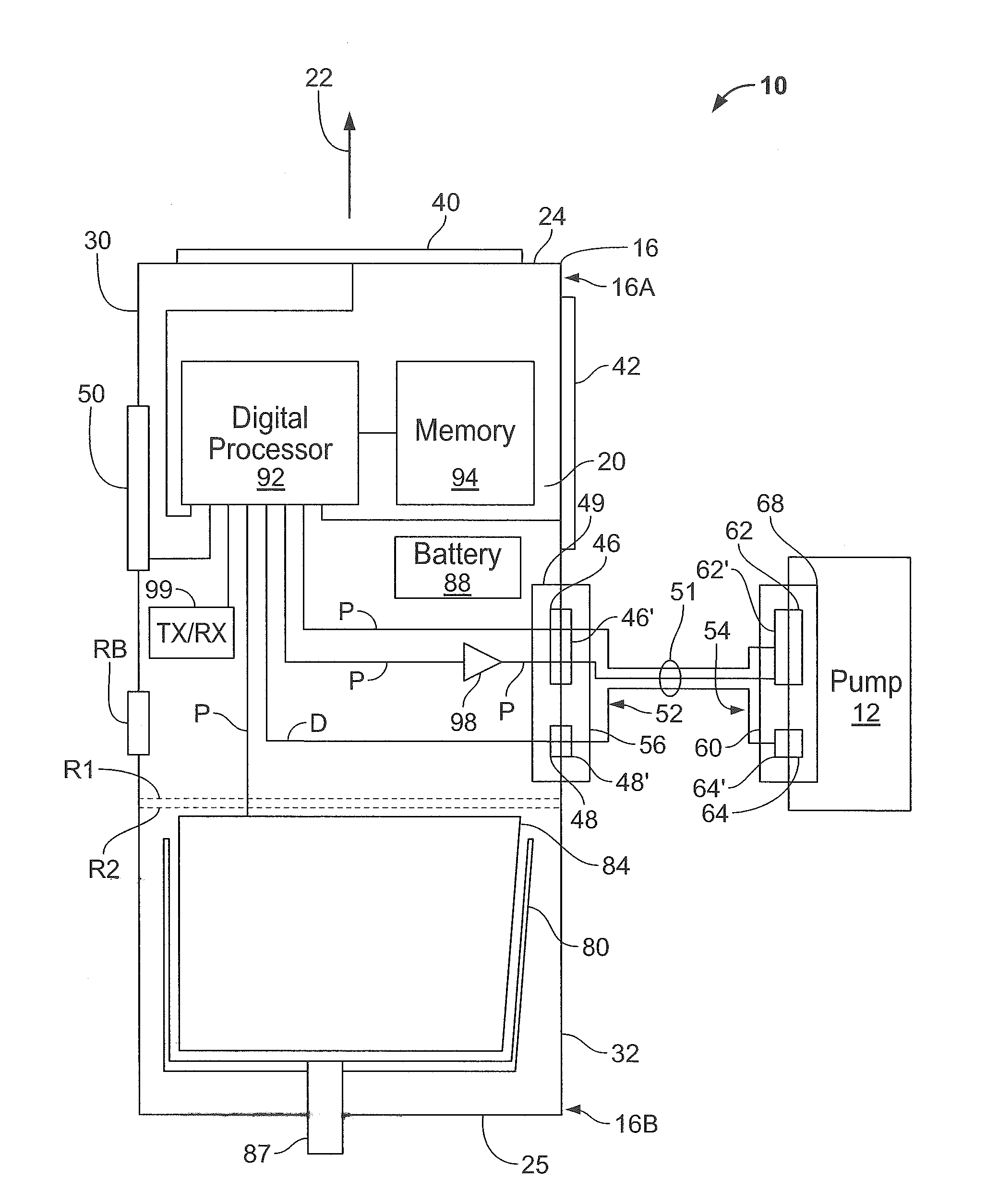
[0025]A control system 10 for controlling the operation of, and providing power for and to, implantable ventricular assist devices which include a pump employing a brushless DC motor-driven blood pump, is shown in FIGS. 1-4. The control system 10 is shown in diagrammatic form in FIG. 5, together with an exemplary pump 12.

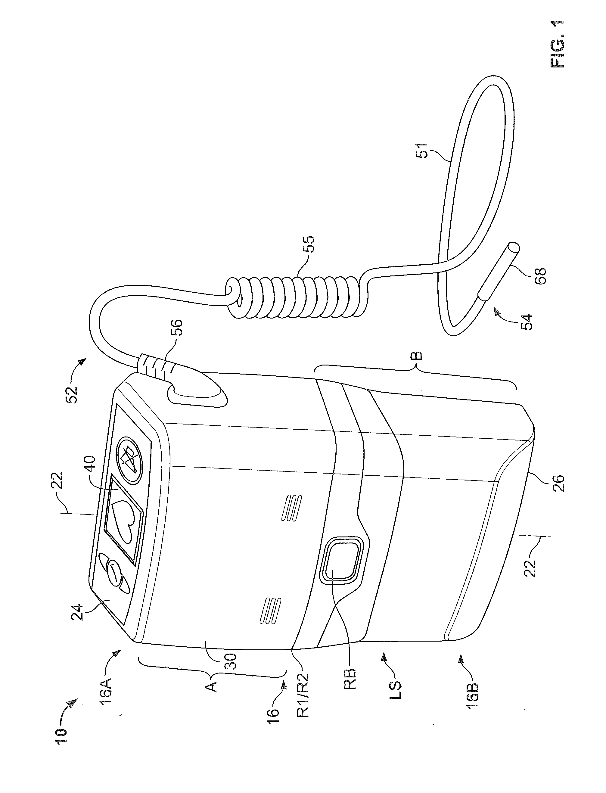
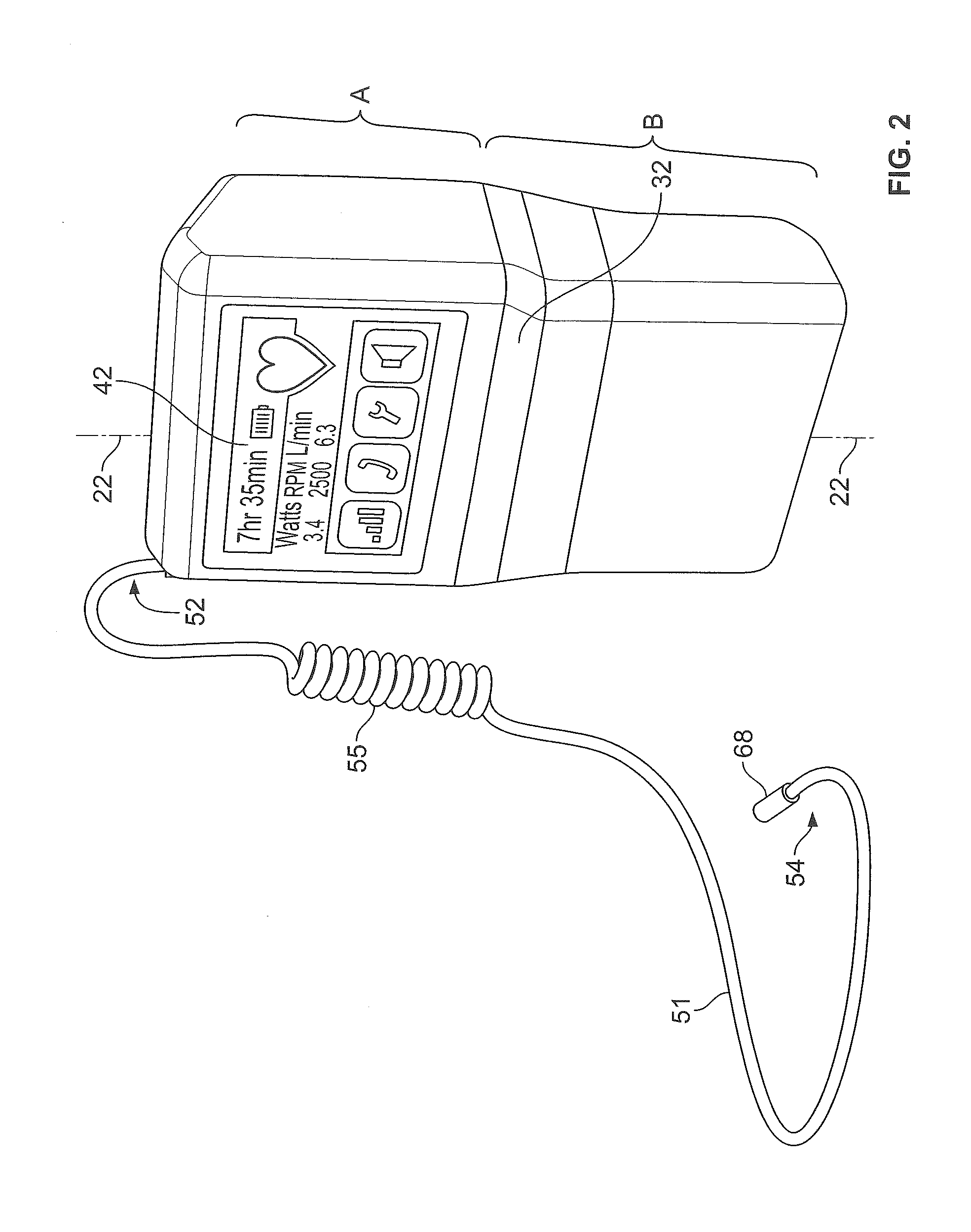
[0026]As shown in FIGS. 1-5, the control system 10 includes a housing 16 disposed about an interior region 20. Housing 16 extends along a housing axis 22 between a top end 16A and a bottom end 16B. At the top end 16A, a top panel 24 having a substantially planar outer surface, extends transverse to the housing axis 22. At the bottom end 16B, a bottom panel 26 having a substantially planar outer surface, extends transverse to the housing axis 22. Lateral surfaces LS of housing 16 extend between the circumferential outer boundary of top panel 24 and the circumferential outer boundary of bottom panel 26. In the aggregate, the lateral surfaces of housing 16 form a tube-...


PUM


Abstract

Methods and apparatus for controlling the operation of, and providing power for and to, implantable ventricular assist devices which include a brushless DC motor-driven blood pump, are disclosed. In one embodiment, a control system for driving an implantable pump is provided. The digital processor is responsive to data associated with the operation of the pump received at the data transfer port, and from the program data stored in memory, (i) to determine therefrom, the identity of the pump, (ii) to determine therefrom, electrical characteristics and features of the identified pump, and (iii) to adaptively generate and apply to the data port, control signals for driving the identified pump. Latch mechanisms, an elongated flexible electrical cable with a strain relief segment, and a lower housing portion that is heavier than an upper housing portion, may also be provided with the control system.

Description

CROSS-REFERENCE TO RELATED APPLICATIONS[0001]The present application claims the benefit of the filing date of U.S. Provisional Patent Application No. 61 / 749,038 filed Jan. 4, 2013, the disclosure of which is hereby incorporated by reference herein.FIELD OF THE INVENTION[0002]This invention relates to the field of implantable medical devices. In particular, this invention is drawn to controllers and power supplies for motor-driven implantable medical device applications.APPLICATIONS INCORPORATED BY REFERENCE[0003]U.S. Patent Publication No. 2012 / 0226350, titled “Controller and Power Source for Implantable Blood Pump” is hereby incorporated by reference herein. U.S. Patent Publication No. 2012 / 0086402, titled “Fault-Tolerant Power Supply” is hereby incorporated by reference herein.BACKGROUND OF THE INVENTION[0004]Implantable medical devices, such as ventricular assist devices, are being developed for long term treatment of chronic heart failure. Such devices require a pumping mechanis...

Claims


Application Information

Patent Timeline
Patent Type & Authority Applications(United States)
IPC IPC(8): A61M1/10
CPCA61M1/1053A61M2205/8206A61M60/148A61M60/411A61M60/216A61M60/508A61M60/178A61M60/876G06F1/3212A61M2205/18A61M2205/44A61M2205/50A61M2205/502A61M2205/52A61M2205/8262G06F1/263
Inventor VADALA, JR., CHARLES JOSEPH
Owner HEARTWARE INC
Why Eureka
Try Eureka