Heat exchange in fluid degassing

a fluid degassing and heat exchange technology, applied in liquid degasification, separation processes, ultrasonic/sonic/infrasonic diagnostics, etc., can solve problems such as animal exposure, failure to properly degas the water, and unnecessary stress and discomfor

Active Publication Date: 2014-07-17
KONINKLIJKE PHILIPS ELECTRONICS NV
View PDF13 Cites 3 Cited by
  • Summary
  • Abstract
  • Description
  • Claims
  • Application Information

AI Technical Summary

Benefits of technology

[0022]Particularly, accumulation of condensed water in the degasser filter cartridge is preventable by aligning it in such a way as to allow water to flow out of it by gravity. Otherwise, the external surface of the semi-permeable tubing in the degasser filter cartridge could be completely submerged in water, preventing it from degassing any additional water.
[0023]Another measure is to actively cool the water vapor to force it to condense into water at room temperature or below as soon as it exits the degasser filter cartridge.

Problems solved by technology

On the one hand, the colder the coupling medium, the more efficiently it removes heat from the HIFU transducer; however, both of the above-described approaches fail to properly degas the water when its temperature is raised above room temperature.
Otherwise, the animal (whose sizes can sometimes be comparable to the larger size of the coupling water bolus) is exposed to unnecessary stress and discomfort, as it tries to up-regulate its metabolism to compensate for its body's heat loss to the (colder) coupling fluid.
This is especially difficult for the animal, which is typically under anesthesia during these procedures, which further hampers its ability to regulate body temperature properly, potentially yielding incorrect experimental conditions and results, especially in pre-clinical experiments that rely on normal blood-flow conditions (i.e., drug delivery experiments).
Small animals (i.e., mice, rats) are particularly at risk of hypothermia, since many of the ultrasound applicators used for pre-clinical research are large with respect to the animal, and can quite effectively act as a heat sink.
Also, since HIFU transducers are typically not 100% efficient, there is a steady warming of the coupling water during a treatment.
While possibly comfortable to the patient, too much warming can cause skin burns and also degrades HIFU ultrasound transducer performance.

Method used


Image

  • Heat exchange in fluid degassing
  • Heat exchange in fluid degassing

Examples


Embodiment Construction

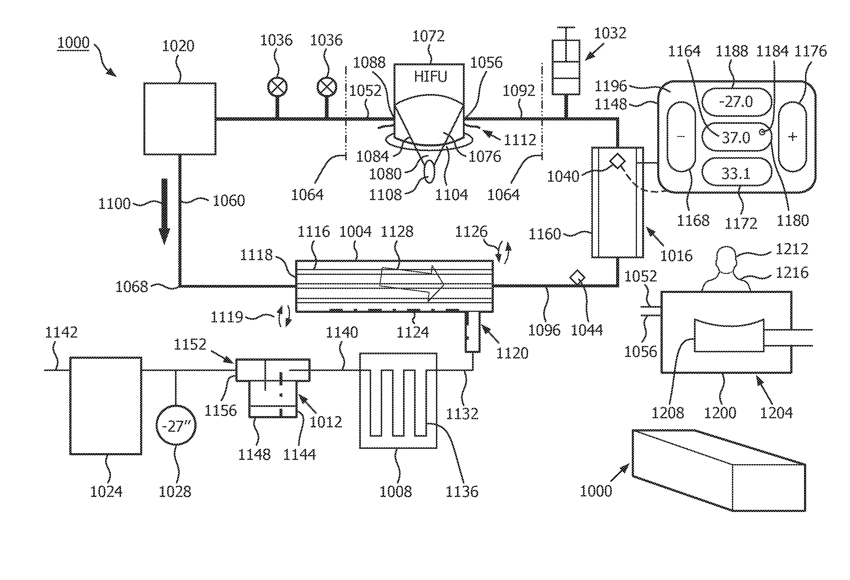
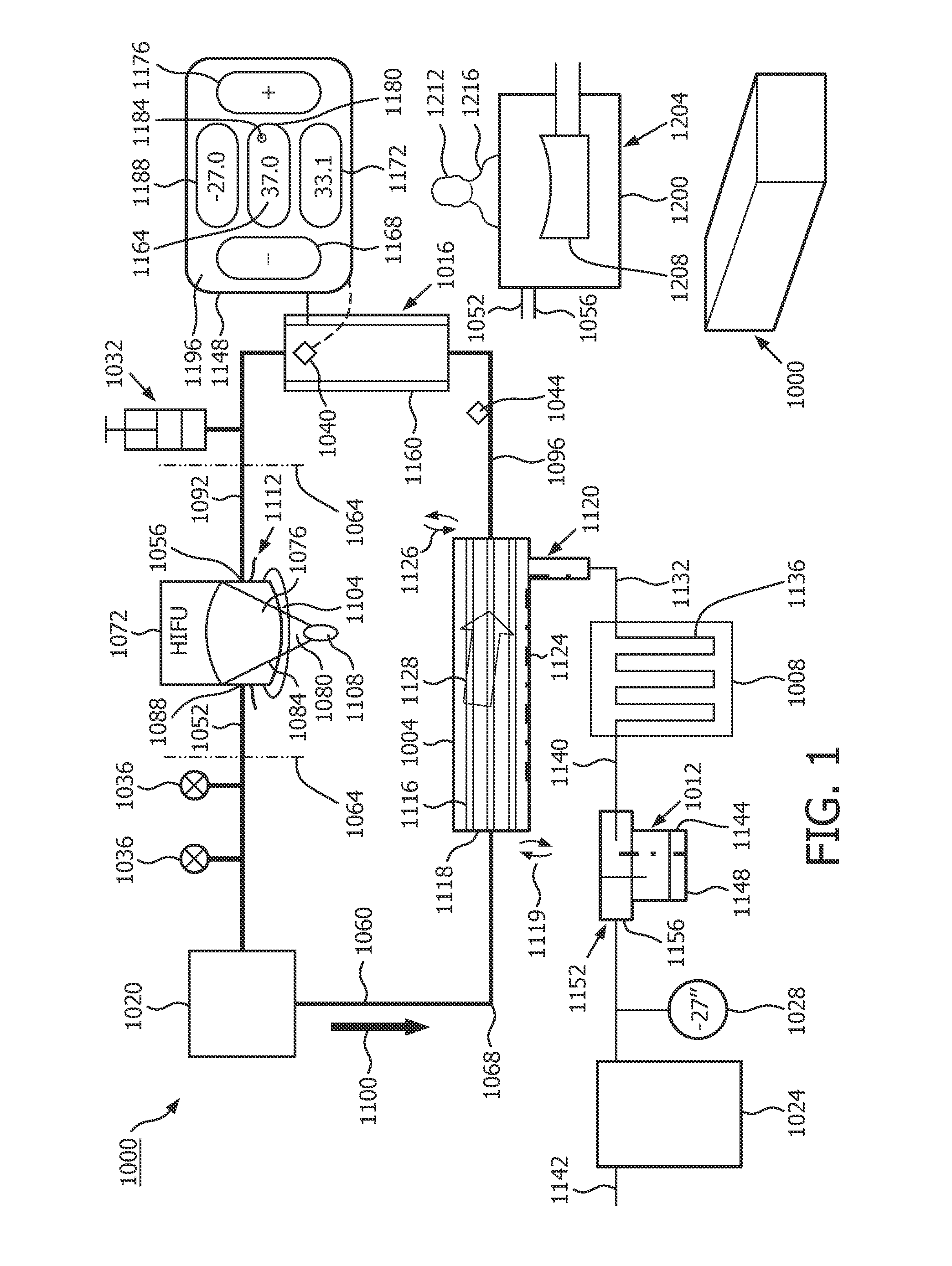
[0052]FIG. 1 shows, by illustrative and non-limitative example, a temperature-control / fluid-degassing device 1000. The embodiment shown in FIG. 1 pertains particularly to an inline device, but also shows components usable in a batch device. An inline device will be discussed first.

[0053]The degassing device 1000 includes a degassing chamber (or “degassing filter cartridge”) 1004. Also included are a cooler 1008 and a water trap 1012. Among the further components of the device 1000 is a heater 1016, a self-priming circulation pump 1020, a vacuum pump 1024, a vacuum gauge 1028, a water-volume-adjustment expansion tank 1032, and system fill / drain valves 1036. An additional component is an on-heater temperature sensor 1040, or alternatively an inline temperature sensor 1044. The device 1000 also includes a user interface 1048 such as a touchscreen; water inlet tubing 1052, water outlet tubing 1056; internal water transit tubing 1060; and a housing 1064. The device 1000 further includes ...


PUM

PropertyMeasurementUnit
operating temperatureaaaaaaaaaa
weightaaaaaaaaaa

Abstract

In one variation, a temperature-maintenance device includes a heater (1016) and is placeable in a circulation loop of an ultrasound transducer coupling bolus (1076), for degassing circulating liquid of the loop and for operating the heater for performing temperature control of the liquid. A temperature setpoint, such as a normal body temperature, for the liquid at the bolus may be entered. A device, either open- or closed-looped with respect to fluid flow, may include, in some variations, a degassing chamber, a water trap (1012), and an intervening cooler, all vacuumized by a vacuum pump (1024). The chamber may be configured and aligned for letting condensation automatically drain out. The water trap may be emptied, automatically and without the need for user intervention, by a motorized trap emptier and/or be emptiable by the user.

Description

FIELD OF THE INVENTION[0001]The present invention relates to degassing a fluid and, more particularly, to a degassing system that utilizes heat exchange.BACKGROUND OF THE INVENTION[0002]A liquid of low viscosity is required to couple high-intensity focused ultrasound (HIFU) transducers to the targeted tissue / organ, e.g., the abdomen, in both clinical and pre-clinical applications. A second, very thin layer of coupling medium, e.g., a gel, intervenes for direct contact with the skin of the patient.[0003]The liquid, such as water, should be relatively pure, with a dissolved oxygen content less than or equal to three parts per million (PPM). Otherwise, the high-intensity focused field can easily create cavitation bubbles in the coupling fluid that could block and / or distort the ultrasound field. Inefficiencies in HIFU transducers are mainly in the form of heat they locally generate. The heat is continuously removed by the liquid coupling medium flowing laterally along and past the face...

Claims


Application Information

Patent Timeline
Patent Type & Authority Applications(United States)
IPC IPC(8): B01D19/00A61B8/00
CPCA61B8/546B01D19/0036
Inventor SEIP, RALFLEYVI, EVGENIYAZEVEDO, JOSE MANUEL INOCENCIO
Owner KONINKLIJKE PHILIPS ELECTRONICS NV
Why Eureka
Try Eureka