
Hot Standby Power Supply for a Variable Frequency Drive

a variable frequency drive and power supply technology, applied in emergency power supply arrangements, motor/generator/converter stoppers, dynamo-electric converter control, etc., can solve the problems of significant delay, frequency converters that trip on under-voltage, and lose the main power supply of the vessel, so as to reduce the blackout of the power system

Inactive Publication Date: 2014-07-17
SIEMENS AG
View PDF10 Cites 15 Cited by
  • Summary
  • Abstract
  • Description
  • Claims
  • Application Information

AI Technical Summary

Benefits of technology

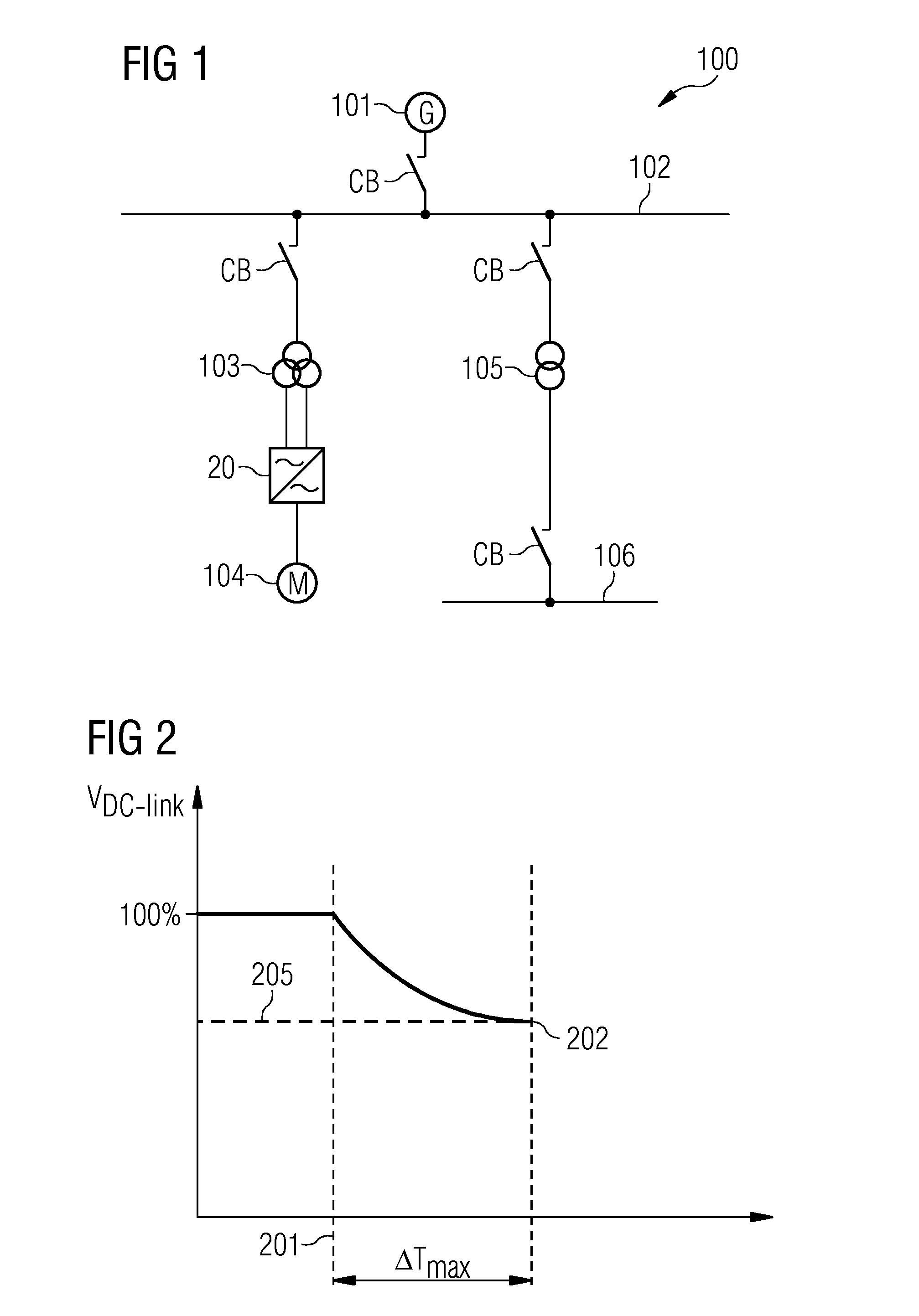
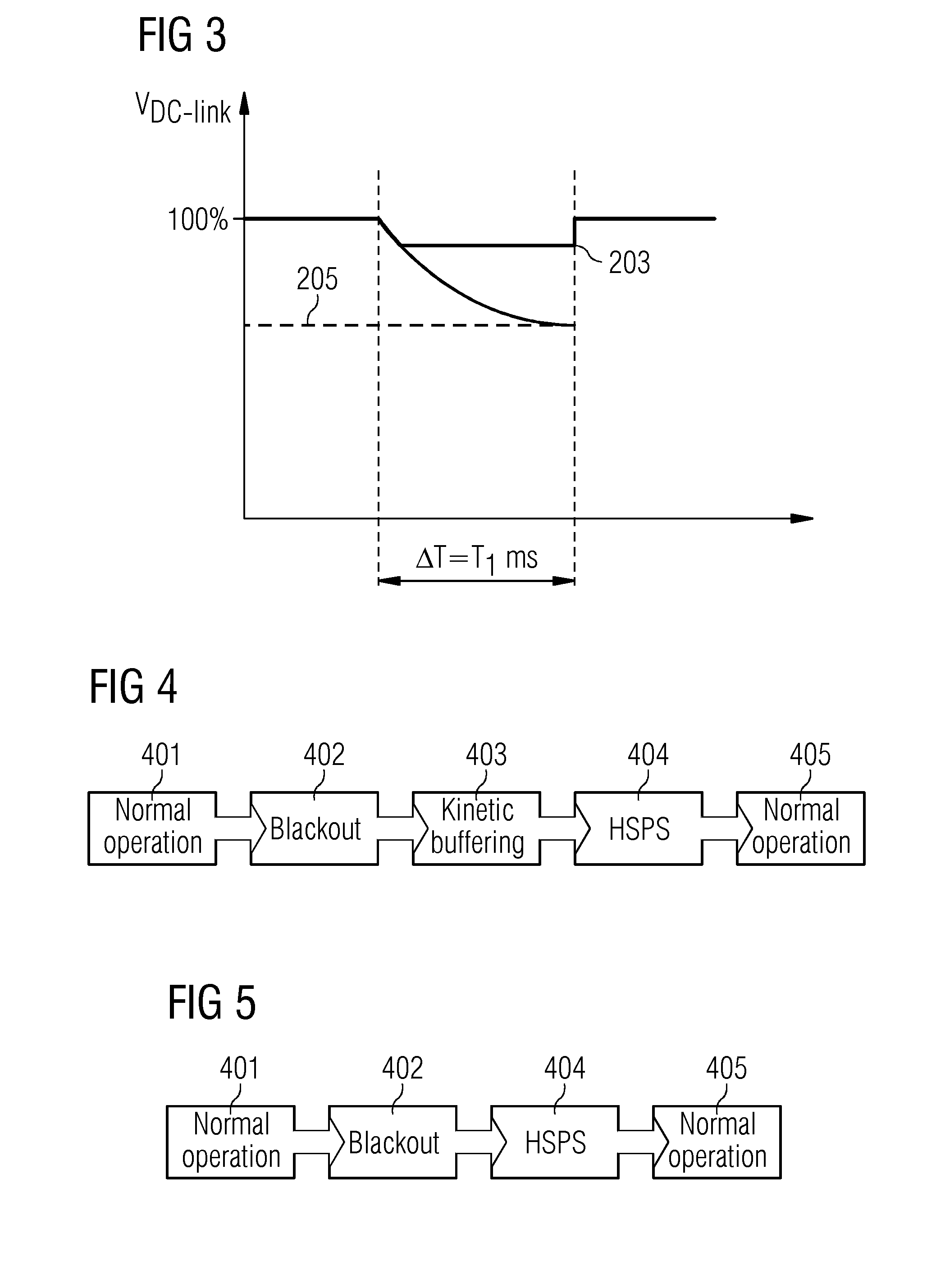
The present invention aims to address the issue of a variable frequency drive (VFD) being unavailable for a lengthy period after a blackout in a power system. The invention provides a solution to mitigate this drawback and make the recovery time of an electrical drive after a blackout as short as possible. Kinetic buffering is also provided to maintain the voltage level on the DC link during a standby mode of the VFD. This results in an increased duration of the standby mode. Overall, the invention improves the reliability and efficiency of the drive system.

Problems solved by technology

If the power plant experiences a blackout, or if there is a fault in the onboard power grid or in a component coupled thereto, the vessel will lose its main power supply.
If a blackout of the main power supply occurs, these frequency converters map trip on under-voltage and may be out of service for the duration of the blackout.
Although the power plants of such vessels may be designed to restore electric power as fast as possible, and the electric drives are designed to restart as fast as possible, there may be a significant delay before the electric drives may continue to operate.
Long delays are undesirable, for example, for marine vessels having electric propulsion systems, as inoperability of the thruster drives may lead to a loss of position and maneuverability.
Operating the vessel with split sections of the power system makes operation rather ineffective and leads to a higher fuel consumption and thus increased operating costs.

Method used


Image

  • Hot Standby Power Supply for a Variable Frequency Drive
  • Hot Standby Power Supply for a Variable Frequency Drive
  • Hot Standby Power Supply for a Variable Frequency Drive

Examples


Embodiment Construction

[0057]In the following, embodiments are described in detail with reference to the accompanying drawings. The following description of the embodiments is given only for the purpose of illustration and is not to be taken in a limiting sense.

[0058]The drawings are schematic representations only, and elements in the drawings are not necessarily to scale with each other. The representation of the various elements is chosen such that function and general purpose of the elements are apparent to a person skilled in the art. The coupling of physical or functional units as shown in the drawings and described hereinafter does not need to be a direct connection or coupling, but may also be an indirect connection or coupling (e.g., a connection or a coupling with one or more additional intervening elements). The skilled person will further appreciate that the physical or functional units illustrated and described herein with respect to the different embodiments do not need to be implemented as p...


PUM


Abstract

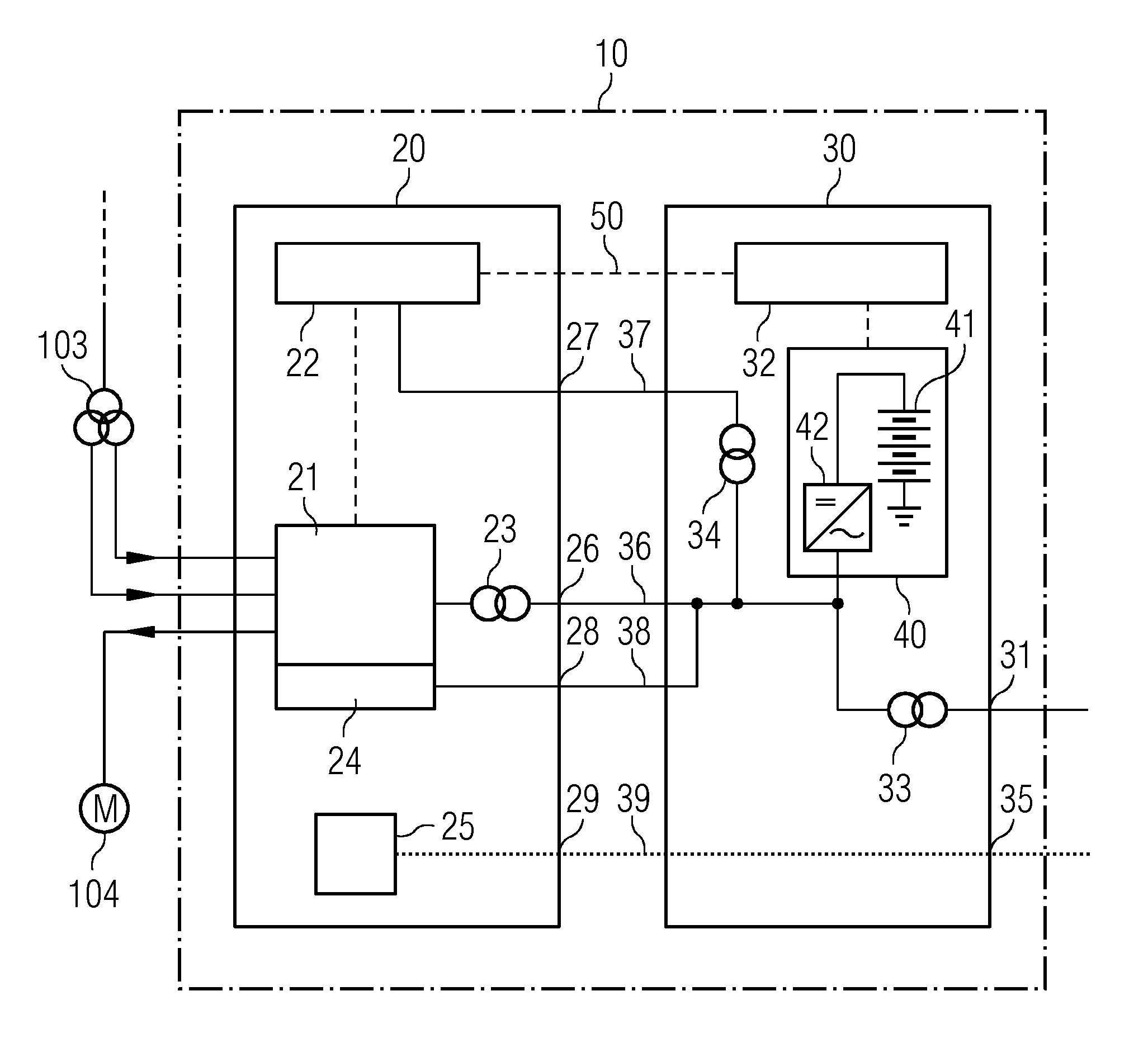
A hot standby power supply for a variable frequency drive of a floating vessel is provided. The variable frequency drive may power an electric motor of the floating vessel. The hot standby power supply includes a power input for receiving electric power from a main power supply of the floating vessel. The hot standby power supply also includes a first electric connection configured to supply electric power at a first voltage level to a converter power input of the variable frequency drive, and a second electric connection configured to supply electric power at a second voltage level to control power input of the variable frequency drive. The first voltage level is higher than the second voltage level. A transformer is further provided for transforming received electric power to the first voltage level or to the second voltage level.

Description

[0001]This application claims the benefit of EP 13151048, filed on Jan. 11, 2013, which is hereby incorporated by reference in its entirety.FIELD[0002]The present embodiments relate to a hot standby power supply for a variable frequency drive of a floating vessel, a corresponding drive system including such a hot standby power supply, and a method of operating a hot standby power supply.BACKGROUND[0003]Some types of floating vessels, such as drill ships, floating platforms, drilling semi-submersibles, floating production storage and off-loading vessels (FPSOs) and the like use electric propulsion systems in which propellers are driven by electrical motors. Examples include azimuth thrusters of a vessel, which include an electric motor arranged in a pot. The electric motor is directly connected to the propeller. Electricity may be produced on board of such vessels, for example, by one or more generators coupled to a diesel engine or gas turbine, and transmitted by an onboard power gr...

Claims


Application Information

Patent Timeline
Patent Type & Authority Applications(United States)
IPC IPC(8): H02P27/04H02M1/00
CPCH02P27/04H02J4/00H02J7/34H02J9/04H02M1/0032Y02B70/10Y02B70/30Y04S20/20
Inventor HAUGEN, JOERN TOREOHMA, HAAVAR FORSELL
Owner SIEMENS AG
Learn More