
Binding element for a building wall structure

a technology for building walls and binding elements, applied in structural elements, building components, pillars, etc., to achieve the effects of good thermal insulation, easy installation of such binding elements, and big toleran

Inactive Publication Date: 2014-07-24
NV BEKAERT SA
View PDF0 Cites 17 Cited by
  • Summary
  • Abstract
  • Description
  • Claims
  • Application Information

AI Technical Summary

Benefits of technology

The present invention relates to a binding element that can be easily installed in a building wall structure. This binding element is made of an elongated steel element coated with a thermoplastic material having a uniform thickness on each straight portion of the steel element. The binding element can be bent without affecting the thickness of the coating. The coating is formed by any available coating method. The binding element can provide better thermal insulation and its thermal conductivity is minimal.

Problems solved by technology

The problem often encountered is the installation of such split hook which is a cumbersome process involving multiple steps such as drilling a hole in the outer wall, hammering the plug in to the hole, installing the metal wire in to the plug, covering the metal wire with a shield, hammer the metal wire in to the plug and removing the shield.
Another disadvantage of this system is strength.

Method used


Image

  • Binding element for a building wall structure
  • Binding element for a building wall structure
  • Binding element for a building wall structure

Examples


Embodiment Construction

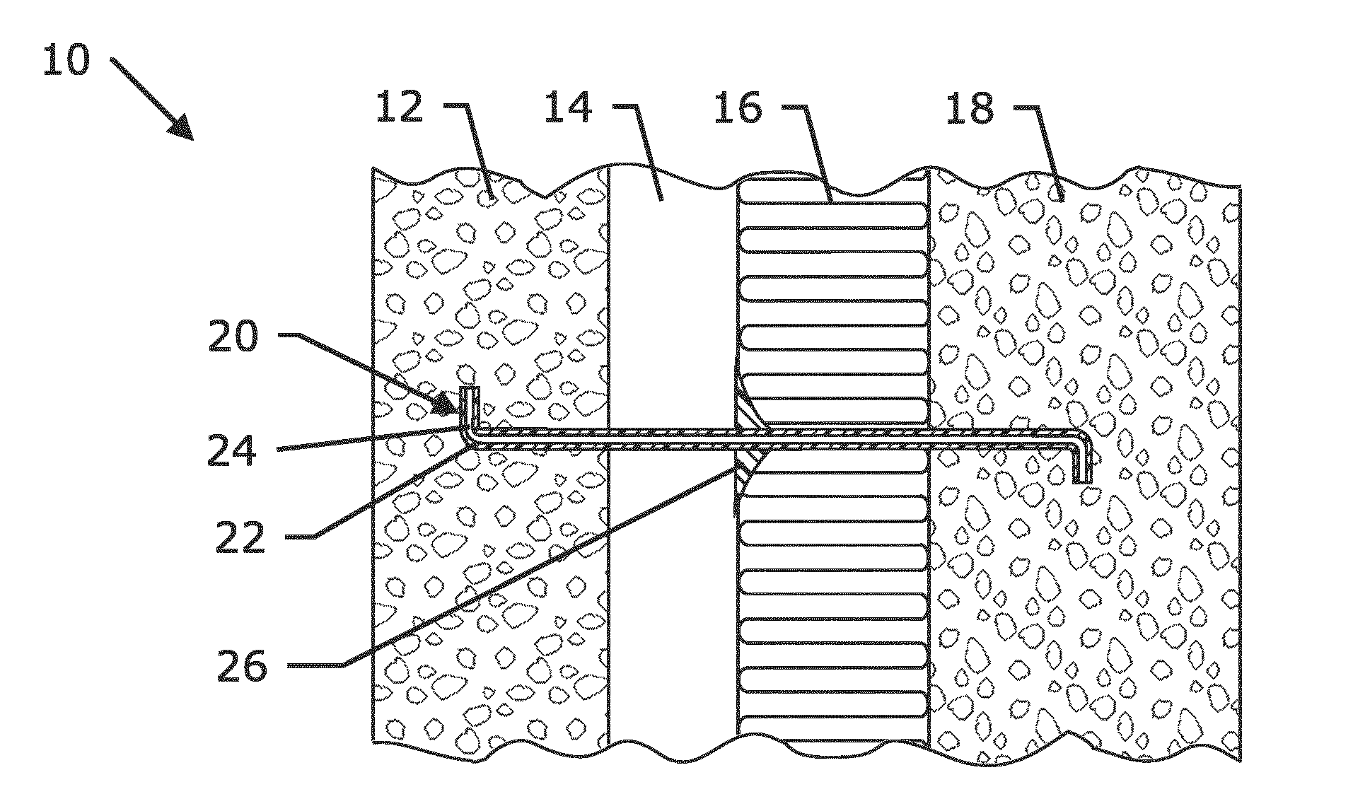
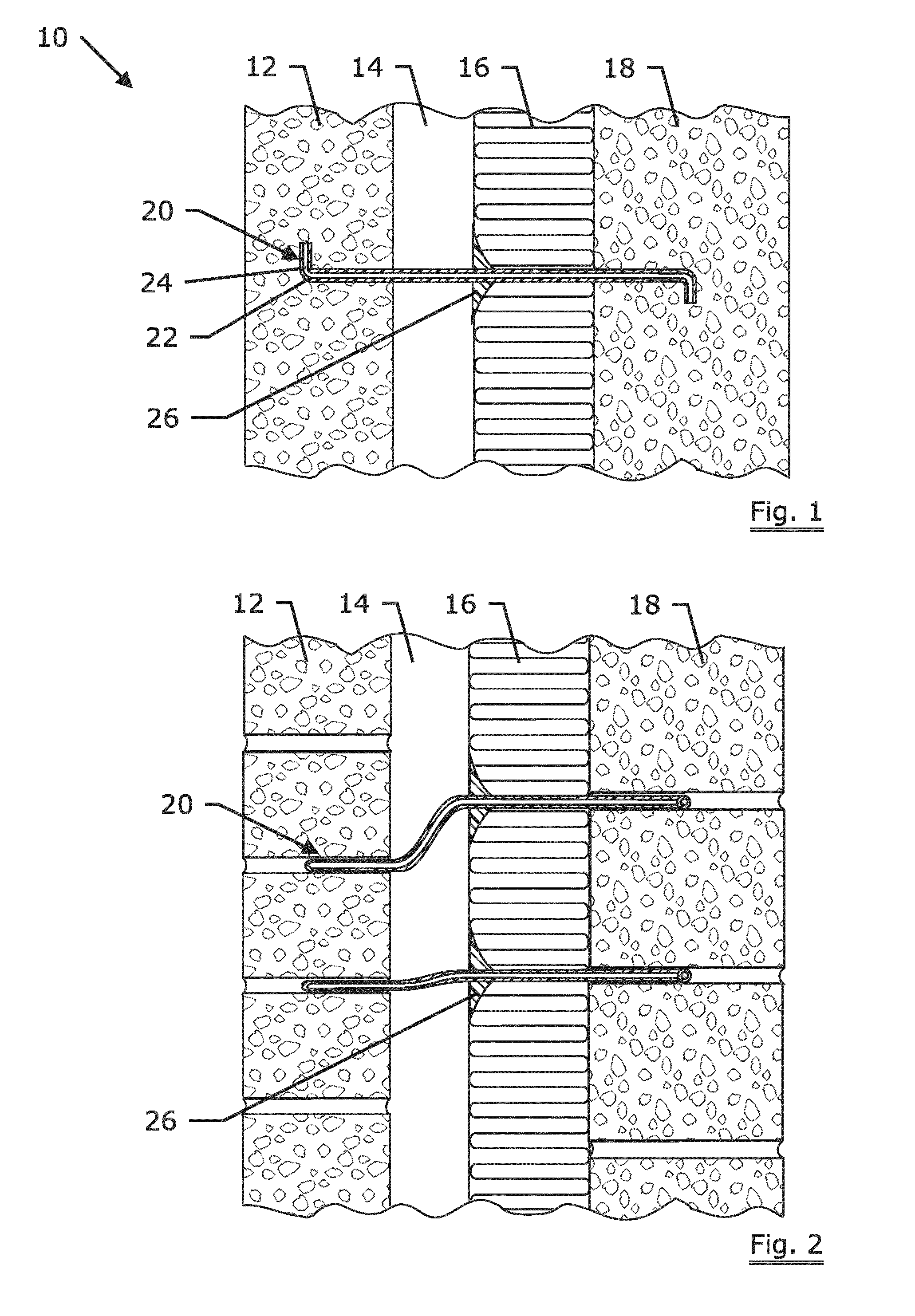
[0011]FIG. 1 depicts a building wall structure of concrete or like composition comprising an inner wall (18), an outer wall (12) spaced from said inner wall and provided with an insulation layer (16) in between, at least one binding element (20) interconnecting said outer wall and inner wall through the insulation layer, the said binding element (20) comprises a elongated steel element (24) preferably having a minimum tensile strength of at least 100 N / mm2 coated with a thermoplastic material (22) of a uniform thickness.

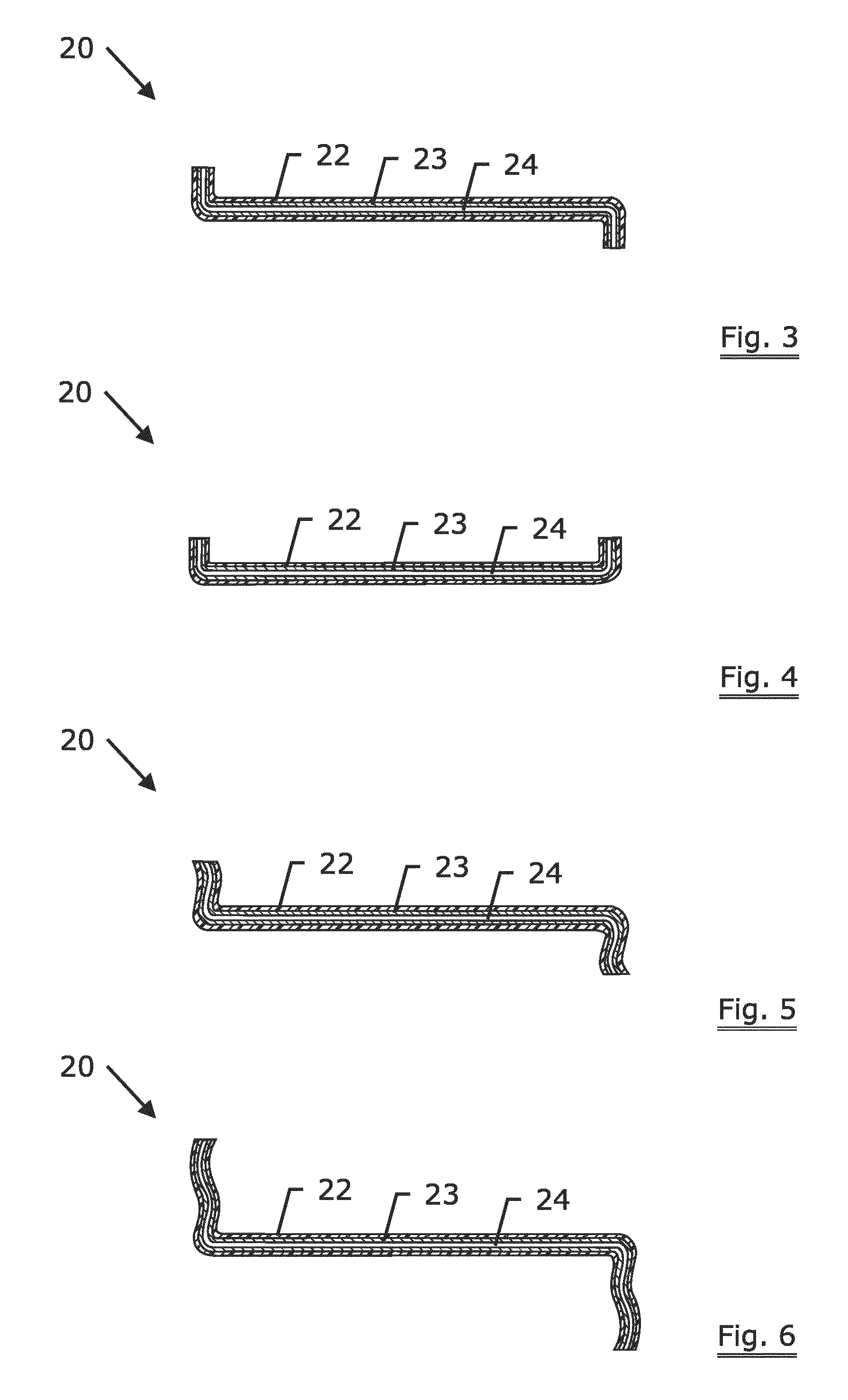
[0012]In one embodiment of the present invention, the elongated steel element (24) is coated with thermoplastic material (22) of a substantially uniform thickness in its entire length and said binding element has two edges and the thermoplastic material is not coated thereon, as shown in FIG. 1 and FIGS. 3 to 6. This configuration can significantly simplify the production process and thus reduce the cost of the binding element. A bundle of steel wire can be first con...


PUM

PropertyMeasurementUnit
diameteraaaaaaaaaa
lengthaaaaaaaaaa
tensile strengthaaaaaaaaaa

Abstract

A binding element for a building wall structure, wherein said binding element comprises an elongated steel element coated with a thermoplastic material, and wherein the coated thermoplastic material has a uniform thickness on each straight portion of the elongated steel element. The building wall structure comprising an inner wall, an outer wall spaced from said inner wall and provided with at least one insulation layer(s) in between, at least one binding element comprising an elongated steel element coated with a thermoplastic material interconnecting said outer wall and inner wall through the insulation layer, wherein ends of said binding element is fixed to the said outer wall and said inner wall respectively and wherein middle portion of said binding element is in contact with the said insulation layer(s). The binding element may comprise a intermediate metallic coating selected from a group consisting of copper, copper alloy, zinc, zinc alloy, nickel, nickel alloy, tin or tin alloy or combinations thereof.

Description

TECHNICAL FIELD[0001]The present invention relates to use of a binding element for a building wall structure, particularly to binding elements having a thermoplastic coating. The binding element has been developed primarily for use in construction industry for wall structures made of concrete, brick, and wood or like composition layers, and will be described hereinafter with reference to this application.BACKGROUND ART[0002]A metal rod that joins and reinforces parts in a structure is well known in the art. Insulated concrete walls are held together with plurality of such metal rods and are widely used in the construction industry for buildings. Galvanized wire was often used as a metal rod for this purpose. In meantime, energy conservation has become a vital component in the construction industry and developments were focused on increasing thermal insulation and reducing cold bridges between outer and inner walls. Hence a split hook was developed which functions as a static connect...

Claims


Application Information

Patent Timeline
Patent Type & Authority Applications(United States)
IPC IPC(8): E04B1/41
CPCE04B1/4178E04B1/4185E04B1/7616
Inventor DE SMET, ANNELEENARDIES, FREDERIK
Owner NV BEKAERT SA
Learn More