Intelligent electric vehicle charging system

Inactive Publication Date: 2014-07-24
RGT UNIV OF CALIFORNIA
View PDF8 Cites 191 Cited by
  • Summary
  • Abstract
  • Description
  • Claims
  • Application Information

AI Technical Summary

Benefits of technology

[0017]The present invention is illustrated in the context of an intelligent automated electric vehicle charging system that can be used with multiple commuter vehicles to be charged in a parking garage or lot. The objective of the invention is to be part of a system that reduces energy cost and usage and increases the stability of loca

Problems solved by technology

Such a system could help substantially with demand response, which is a key and yet challenging problem for electric utilities.
Studies have shown that the di

Method used


Image

  • Intelligent electric vehicle charging system
  • Intelligent electric vehicle charging system
  • Intelligent electric vehicle charging system

Examples


example 1

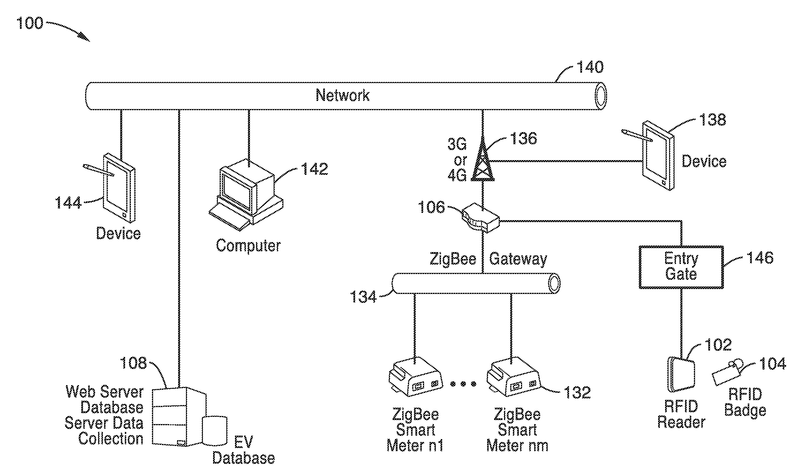
[0065]To demonstrate the functionality of the system, network architecture for EV charging with RFID in a university campus setting was created. The network 100 shown in FIG. 3 was used to test the system elements. Although only one local parking garage network is shown in FIG. 3, it will be understood that many different garage networks can be associated and controlled by control computer programming.

[0066]In the embodiment 100 shown in FIG. 3, the EV is identified at an access point to a garage or lot by way of an RFID reader 102 and an RFID tag or badge 104 that is either attached to the EV or a conventional RFID badge. An RFID programming module and RFID reader 102 at access gate 146 is used to read an EV user's RFID badge 104 and evaluate the available inventory of charging stations. Data from the RFID reader 102 is sent to the command server 108 through gateway 106.

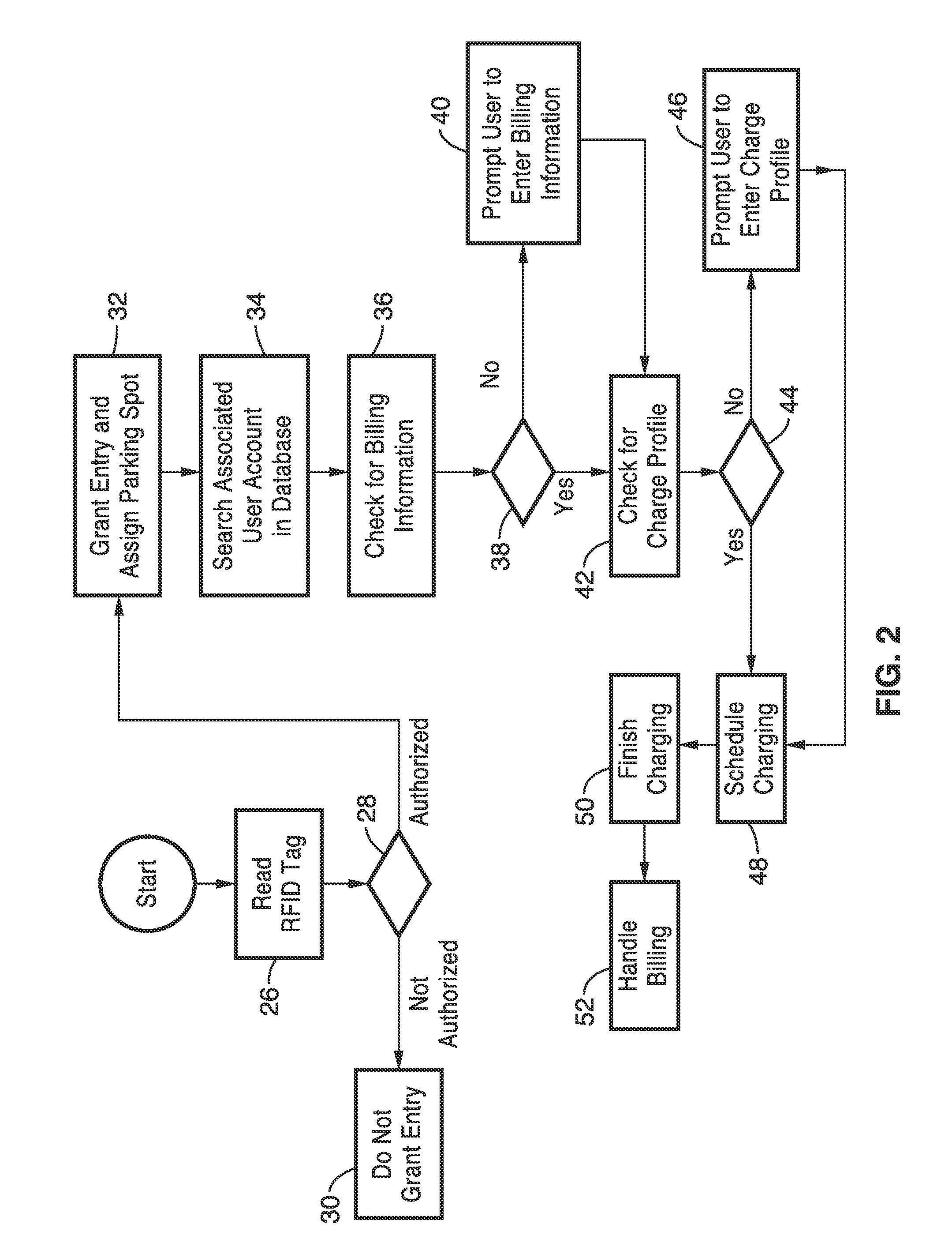
[0067]Referring also to FIG. 4A and FIG. 4B, the RFID tag or tags 104 are used to grant access to the garage and ...

example 2

[0079]To further demonstrate the functionality of the system, a control circuit was designed and tested. Turning now to FIG. 5 and FIG. 6, a microcontroller circuit diagram and block diagram are schematically shown. Generally, a wireless ZigBee or Wi-Fi mesh network is established that is connected to a control server through a gateway.

[0080]In this embodiment, an Arduino R3 microcontroller 200 with associated RFID and ZigBee devices and signal flow is generally shown. The microcontroller 200 receives input from the RFID reader 202. A ZigBee network processor 204 is also operably coupled to the microcontroller 200. The processor 204 is in wireless communication with at least one other ZigBee network processor 206. Although only end device processor 204 is shown associated with coordinator controller 206, many devices can be used to form mesh network. The mesh network is connected to a gateway 208 that preferably communicates through the Internet 210 through Wi-Fi / 3G or LAN systems w...


PUM


Abstract

A battery charging system for an electric vehicle in which an addressable RFID tag, an RFID receiver, an electrical charger, and a controller operate to charge the battery of an electric vehicle according to a user profile and a charging profile in response to a signal received by the RFID reader from the RFID tag. In an interconnected system, multiple charging stations are connected to the electrical power grid and communicate with a central controller through communications links. A grid converter can be provided to allow for backfilling power from an electric vehicle to the power grid in response to a command from the central controller.

Description

CROSS-REFERENCE TO RELATED APPLICATIONS[0001]This application is a 35 U.S.C. §111(a) continuation of PCT international application number PCT / US2012 / 04393 filed on Aug. 2, 2012, incorporated herein by reference in its entirety, which claims the benefit of U.S. provisional patent application Ser. No. 61 / 514,408 filed on Aug. 2, 2011, incorporated herein by reference in its entirety.[0002]The above-referenced PCT international application was published as PCT International Publication No. WO 2013 / 019989 on Feb. 7, 2013 and republished on May 2, 2013, which publications are incorporated herein by reference in their entireties.STATEMENT REGARDING FEDERALLY SPONSORED RESEARCH OR DEVELOPMENT[0003]This invention was made with Government support under Grant No. DE-OE0000192, awarded by the United States Department of Energy. The Government has certain rights in this invention.INCORPORATION-BY-REFERENCE OF MATERIAL SUBMITTED ON A COMPACT DISC[0004]Not ApplicableBACKGROUND OF THE INVENTION[00...

Claims


Application Information

Patent Timeline
IPC IPC(8): B60L11/18
CPCB60L11/1824B60L2210/40B60L2240/70Y02T90/16Y04S10/126Y04S30/14H02J7/0047Y04S30/12B60L53/64B60L55/00B60L53/63B60L53/65B60L53/665B60L53/305H02J7/00045H02J7/0071H02J13/00012H02J7/00034H02J2310/48H02J13/00002H02J3/322H02J13/00024H02J13/00026H02J13/00028Y02E60/00Y02T10/70Y02T10/7072Y02T10/72Y02T90/12Y02T90/167Y04S40/126Y04S20/221Y02B70/30Y02B90/20H02J7/0048B60L53/30H02J7/00H02J13/00Y02T90/14
Inventor GADH, RAJITCHATTOPHADHYAY, ARUNABHCHUNG, CHING-YENCHU, PETERPRABHU, BRAHMAVARSHEIKH, OMARCHYNOWETH, JOSH
Owner RGT UNIV OF CALIFORNIA
Why Eureka
Try Eureka