Inductive detection type rotary encoder
a rotary encoder and inductive detection technology, applied in the field of rotary encoders, can solve the problems of proportionately more complex wiring patterns and increasing circuit scale, and achieve the effects of reducing crosstalk, improving measurement accuracy, and reducing the number of components
- Summary
- Abstract
- Description
- Claims
- Application Information
AI Technical Summary
Benefits of technology
Problems solved by technology
Method used
Image


Examples
first embodiment
1. First Embodiment
1-1. Overall Configuration
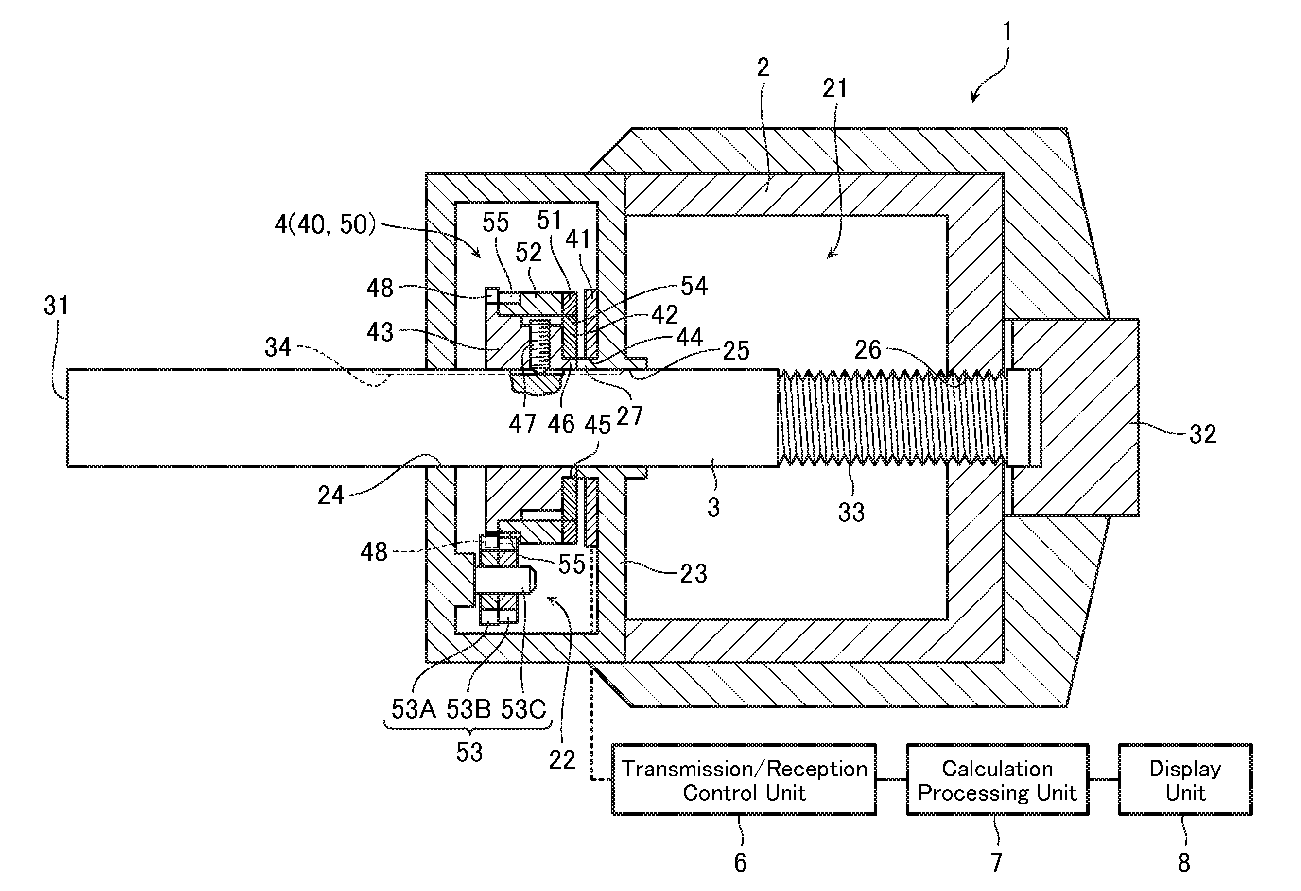
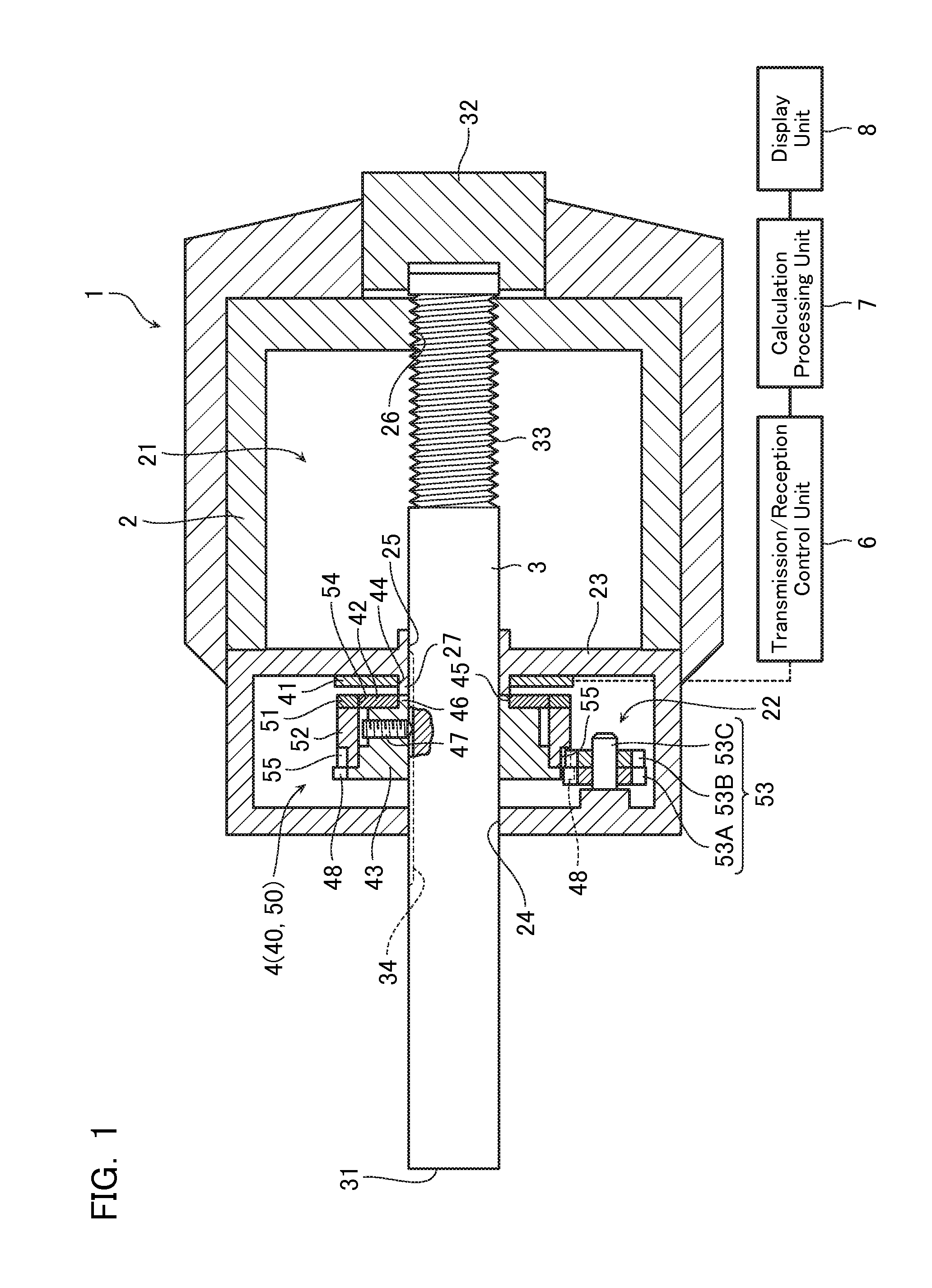
[0057]First, an overall configuration of a micrometer head 1 having mounted therein an inductive detection type rotary encoder 4 according to a first embodiment will be described with reference to FIG. 1. FIG. 1 is a cross-sectional view showing the micrometer head 1 according to the first embodiment.
[0058]The micrometer head 1 includes a main body 2, a spindle 3 extending from the main body 2, and the inductive detection type rotary encoder 4 provided around the spindle 3. In addition, the micrometer head 1 includes a transmission / reception control unit 6, a calculation processing unit 7, and a display unit 8. The transmission / reception control unit 6 controls transmission / reception of signals to / from the inductive detection type rotary encoder 4. The calculation processing unit 7 executes calculation processing based on a signal from the transmission / reception control unit 6 (the inductive detection type rotary encoder 4). The display u...
second embodiment
2. Second Embodiment
[0112]Next, an inductive detection type rotary encoder 4-2 according to a second embodiment of the present invention will be described. In the first embodiment, an ABS type inductive detection type rotary encoder 4 of a configuration including two tracks was described, but in the second embodiment, an ABS type inductive detection type rotary encoder 4-2 of a configuration including four tracks will be described.
[0113]As shown in the first embodiment, for example, when it is assumed that one reception winding is configured from a group of three wirings, then each time the number of tracks increases by one, the number of lead-out wirings increases by six at a time. Therefore, normally when an ABS type inductive detection type rotary encoder having four tracks is configured, as many as 24 lead-out wirings become required for the reception windings. Therefore, a large amount of wiring space becomes necessary, and furthermore, a circuit scale of the control circuit al...
third embodiment
3. Third Embodiment
3-1. Configuration of Inductive Detection Type Rotary Encoder 4-3 According to Third Embodiment
[0126]Next, a configuration of an inductive detection type rotary encoder 4-3 according to a third embodiment will be described. The inductive detection type rotary encoder 4-3 according to the present embodiment is substantially similar to the inductive detection type rotary encoder 4-2 according to the second embodiment, but a configuration of a stator 41-3 thereof is different. That is, as shown in FIG. 16, the stator 41-3 of the inductive detection type rotary encoder 4-3 according to the present embodiment is configured omitting the third transmission winding S3, and has the second transmission winding S2 configured as a common transmission winding employed in the second and third angle detection tracks. Therefore, the inductive detection type rotary encoder according to the present embodiment has a smaller number of components and can adopt a simpler configuration ...
PUM
 Abstract
Description
Claims
Application Information
 - R&D Engineer
- R&D Manager
- IP Professional
- Industry Leading Data Capabilities
- Powerful AI technology
- Patent DNA Extraction
Browse by: Latest US Patents, China's latest patents, Technical Efficacy Thesaurus, Application Domain, Technology Topic.
© 2024 PatSnap. All rights reserved.Legal|Privacy policy|Modern Slavery Act Transparency Statement|Sitemap