
Process for preparing a multi-layer electrochromic structure

Inactive Publication Date: 2014-07-24
KINESTRAL TECH
View PDF16 Cites 72 Cited by
  • Summary
  • Abstract
  • Description
  • Claims
  • Application Information

AI Technical Summary

Benefits of technology

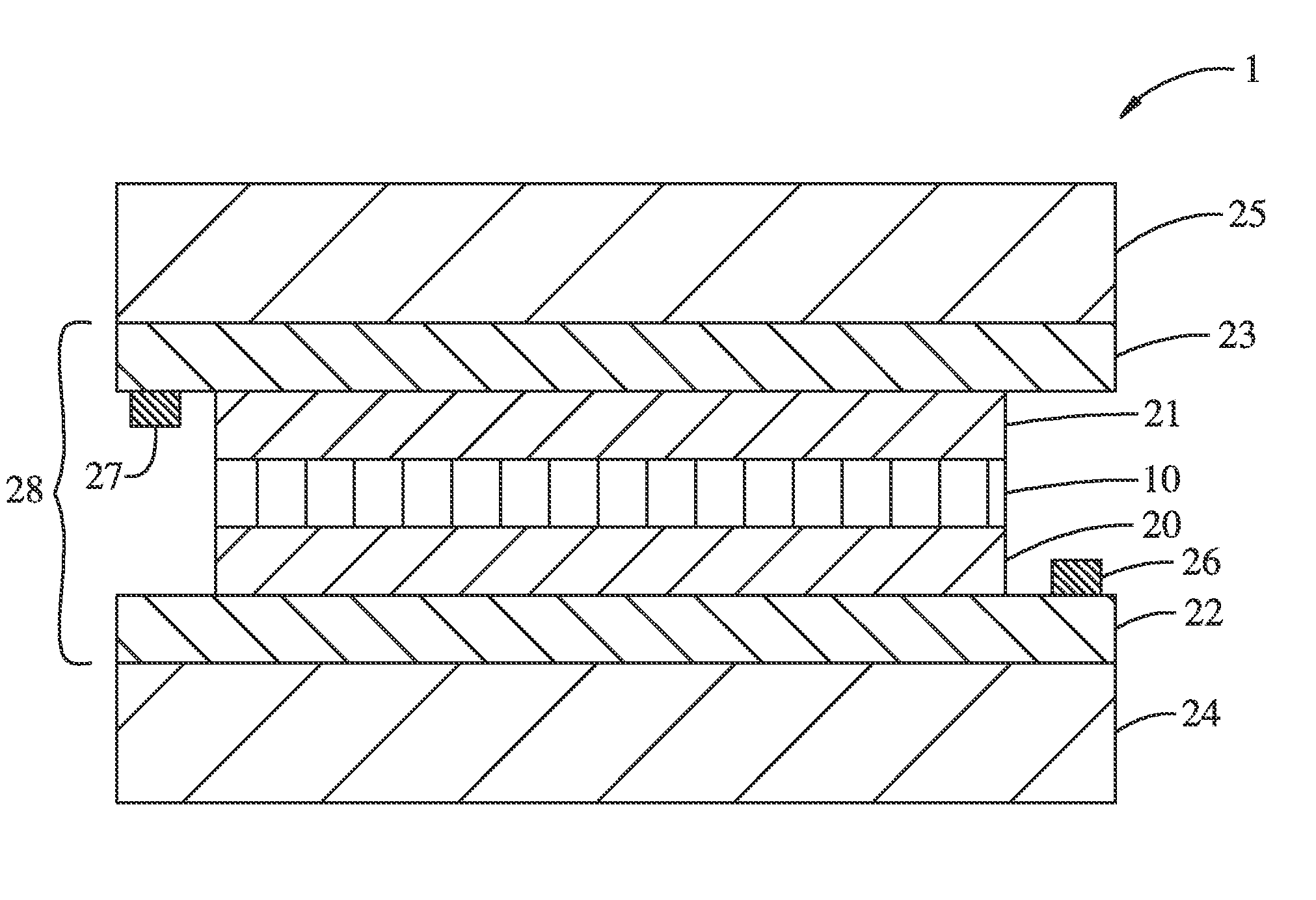
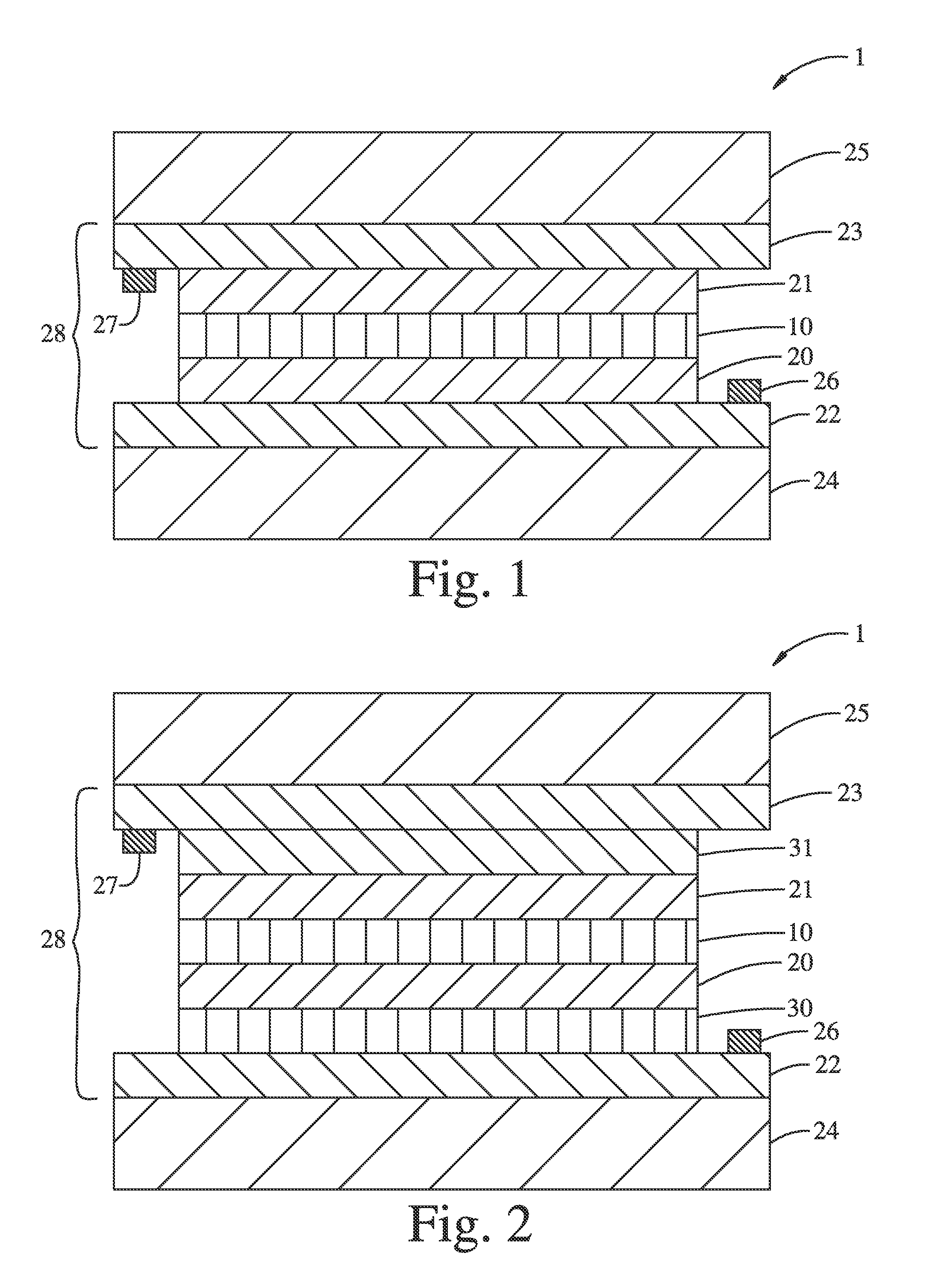
The present invention provides a process for preparing a multi-layer electrochromic structure that includes an anodic electrochromic layer on a substrate. The process involves depositing a film of a liquid mixture onto a surface and treating it to form the anodic electrochromic layer. The resulting structure has several technical effects, including a larger d-spacing of at least 2.5 Å in the anodic electrochromic layer, a bleached state stabilizing element selected from the group consisting of Y, Ti, Zr, Hf, V, Nb, Ta, Mo, W, B, Al, Ga, In, Si, Ge, Sn, P, Sb, and combinations thereof, and an atomic ratio of lithium to the combined amount of nickel and the bleached state stabilizing element(s) in the anodic electrochromic layer that is at least about 0.4:1. The invention also provides a multi-layer electrochromic structure comprising a first substrate and a second substrate, a first and second electrically conductive layer, a cathode layer, an anodic electrochromic layer, and an ion conductor layer. The anodic electrochromic layer comprises lithium, nickel, and at least one bleached state stabilizing element selected from the group consisting of Y, Ti, Zr, Hf, V, Nb, Ta, Mo, W, B, Al, Ga, In, Si, Ge, Sn, P, Sb, and combinations thereof. The invention also provides a process for preparing a multi-layer electrochromic structure comprising an anodic electrochromic film.

Problems solved by technology

If not, electron transfer will occur between the electrode materials and the other window components causing, for example, leakage current, electrolyte consumption, buildup up of reaction products on the electrode (s) and, in general, significantly shortening the useful lifespan of the window.
Li / Li+, lowering their electrical performance and darkening the material.
The proximity of the bleached state voltage to such degrading mechanisms presents significant device control issues: methods will be required to consistently drive the device to the bleached state without driving the anode into damaging voltage regimes accommodating, for example, issues such as local electrode inhomogeneity.
Furthermore, the bleached state lithiated nickel oxide cannot typically be handled in air without the material performance degrading.

Method used


Image

  • Process for preparing a multi-layer electrochromic structure
  • Process for preparing a multi-layer electrochromic structure
  • Process for preparing a multi-layer electrochromic structure

Examples


example 1

Synthesis of Hydrolysable Ni Precursor

[0144]Hydrolysable Ni(II) precursor compound (Ni(DMAP)2) has been synthesized by a modification of the known method (Hubert-Pfalzgraf et. al. Polyhedron, 16 (1997) 4197-4203.) To an anhydrous toluene solution (200 mL) of pre-dried N,N-dimethylamino-2-propanol (8.17 g, 0.0787 mol), was added NaH (1.92 g, 0.0800 mol) by small portions in a N2-purged glove box. The mixture was stirred at room temperature for 2 h until it became clear. To this solution was added Ni(NH3)6Cl2 (9.0 g, 0.039 mol), and it was heated at 80° C. for 6 h, affording a dark green solution. Then the solution was evaporated to dryness under reduced pressure, and the resulting solid was re-dissolved in THF (˜300 mL) which then was filtered through a gravity funnel. Dark green filtrate solution was concentrated to ⅓ of the initial volume, diluted with Hexanes (50 mL) and then cooled in a freezer (˜20° C.). Green needle-shape microcrystals were obtained after one day, which were fi...

example 2

LiNiO2 Film Synthesis

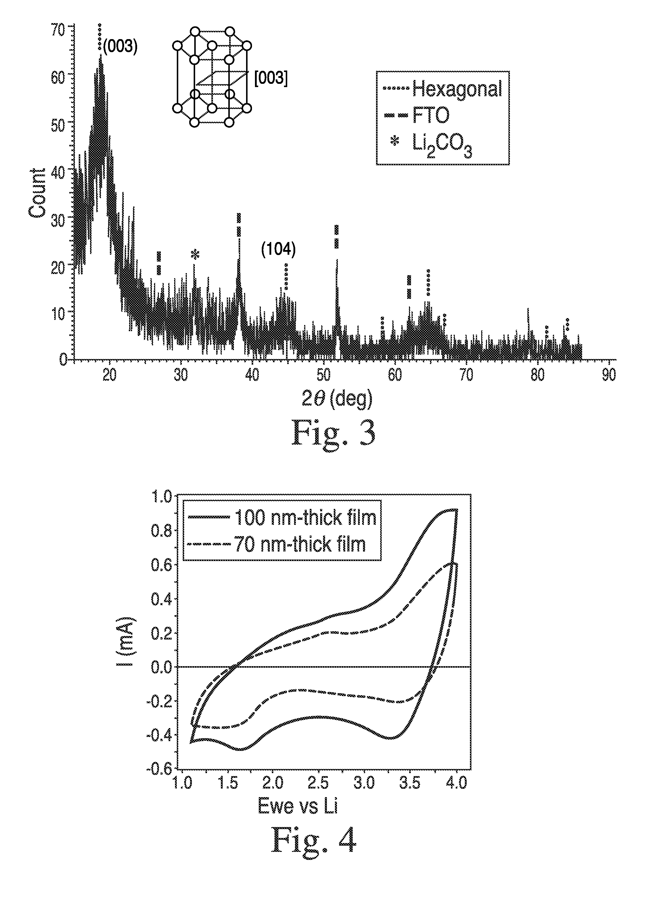
[0145]In a 20 mL-scintillated vial, were added NiDMAP (70 mg), LiOMe (11 mg) and anhydrous MeOH (0.6 mL), affording a dark red solution. Then, electrically conductive FTO (fluorinated tin oxide, 20 mm×20 mm×2 mm) coated glass was loaded in a spin-coater in the glove box. Onto the FTO substrate, was dispensed 0.3 mL of the precursor solution through a 0.2 μm filter and spun at 2500 rpm for 1 min. Sealed in a container in order to avoid air-exposure (CO2 and moisture), the coated film was taken out of the box and was hydrolyzed under warm moisture (45° C.) for 1 h in a N2-filled glove bag. Then it was transferred into an O2-purged tube furnace and subsequently dehydrated under O2 at 400° C. for 1 h. After being cooled down, film thickness was measured as 70 nm by profilometry. Structural phase of the coated film was determined by thin-film XRD measurement, which was identified as hexagonal layered LiNiO2 phase exhibiting an intense peak at 28=18.79° corresponding ...

example 3

Li2NiO2 Clear Film Synthesis

[0146]In order to isolate the clear state Li2NiO2, a LiNiO2 film (100 nm thick) prepared as described in Example 2, was electrochemically reduced by cycling between 1.1 and 4.0 V in the electrochemical cell under Ar-atmosphere and stopping at 1.1 V. Then, the film was taken out of the Ar-box, and was exposed to air while its thin-film XRD was collected by Bruker d8 Advance. After that, the film was brought back into the Ar-glove box, and EC cycling was carried out, which gave result in negligible current flow with no optical transmission change at 550 nm.

[0147]Then, another LiNiO2 film was prepared in the same method as Example 2, and was cycled 5 times between 1.1 and 4.0 V in the electrochemical cell under Ar-atmosphere, affording charge capacity estimated to 23 mC / cm2. The cycling was stopped at 3.6 V, and the film was isolated and subsequently immersed in a freshly-prepared solution of Lithium Benzophenone in THF (deep blue solution) without exposure ...


PUM


Abstract

Process for preparing a multi-layer electrochromic structure comprising depositing a film of a liquid mixture onto a substrate and treating the deposited film to form an anodic electrochromic layer comprising a lithium nickel oxide composition, the anodic electrochromic layer comprising lithium, nickel and the bleached state stabilizing element(s) wherein in the film (i) the ratio of lithium to the combined amount of nickel and the bleached state stabilizing element(s) is at least 0.4:1, (ii) the ratio of the combined amount of the bleached state stabilizing element(s) to the combined amount of nickel and the bleached state stabilizing elements in the lithium nickel oxide composition is at least about 0.025:1, and (iii) the bleached state stabilizing element(s) is / are selected from the group consisting of Y, Ti, Zr, Hf, V, Nb, Ta, Mo, W, B, Al, Ga, In, Si, Ge, Sn, P, Sb and combinations thereof.

Description

FIELD OF THE INVENTION[0001]The present invention generally relates to a process for the preparation of multi-layer electrochromic structures comprising lithium nickel oxides. More particularly, and in one preferred embodiment, the present invention is directed to a process for preparing lithium nickel oxide films for switchable electrochromic multi-layer devices.BACKGROUND OF THE INVENTION[0002]Commercial switchable glazing devices, also commonly known as smart windows and electrochromic window devices, are well known for use as mirrors in motor vehicles, aircraft window assemblies, sunroofs, skylights, and architectural windows. Such devices may comprise, for example, active inorganic electrochromic layers, organic electrochromic layers, inorganic ion-conducting layers, organic ion-conducting layers and hybrids of these sandwiched between two conducting layers. When a voltage is applied across these conducting layers the optical properties of a layer or layers in between change. S...

Claims


Application Information

Patent Timeline
IPC IPC(8): G02F1/153G02F1/1524
CPCG02F1/153G02F1/1524
Inventor CHOI, HYE JINBAILEY, MARKBASS, JOHN DAVIDVON KUGELGEN, STEPHEN WINTHROPLACHMAN, ERICTURNER, HOWARD W.BIGI, JULIAN P.
Owner KINESTRAL TECH
Learn More