Method and control device for operating a magnetic resonance system

a magnetic resonance imaging and control device technology, applied in measurement devices, instruments, acoustic wave reradiation, etc., can solve the problems of tesla, limited acquisition period of tse sequence, and currently inability to allow sar exposur

Active Publication Date: 2014-07-31
SIEMENS HEALTHCARE GMBH
View PDF4 Cites 46 Cited by
  • Summary
  • Abstract
  • Description
  • Claims
  • Application Information

AI Technical Summary

Benefits of technology

[0014]An object of the present invention is to provide a method for operating a magnetic resonance imaging system that, among other things, is suitable for diffusion-weighted imaging, as well as

Problems solved by technology

This results in the fact that the acquisition period of a TSE sequence, especially at field strengths starting at 3 tesla, is usually limited by the SAR and not by the performance capacity of the MR system (for example, the gradient system).
In so-called ultra-high field systems with field strengths of 7T and more, the SAR exposure currently does not allow for performing an examination with a TSE sequence, with an adequate number of slices to cover the anatomy to be examined and in a clinically acceptable measuring time.
However, due to the previously mentioned SAR problems, such new TSE sequence technology with a possibility of simultaneously acquiring several slices is only able to reduce the actual examination period if the radio-frequency radiation per time is at least not increasing.
A further problem in designing such new TSE sequences involves the fact that the refocusing pulses are usually not perfect 180-degree pulses.
Another inherent reason that is unavoidable involves the fact that because of the finite duration of the RF pulses the slice profile does not exactly have a rectangular shape and therefore deviates from the ideal 180 degrees, at least at the edges of the slices.
When these spins accumulate different phase proportions along the different coherent echo paths, it results in destructive interference.
The signal collapses, the images calculated from the raw data show shadows and a poor signal to noise ratio (SNR), and the pulse frequency is not able to maintain a long echo train.
However, by spoiling spec

Method used


Image

  • Method and control device for operating a magnetic resonance system
  • Method and control device for operating a magnetic resonance system
  • Method and control device for operating a magnetic resonance system

Examples


Embodiment Construction

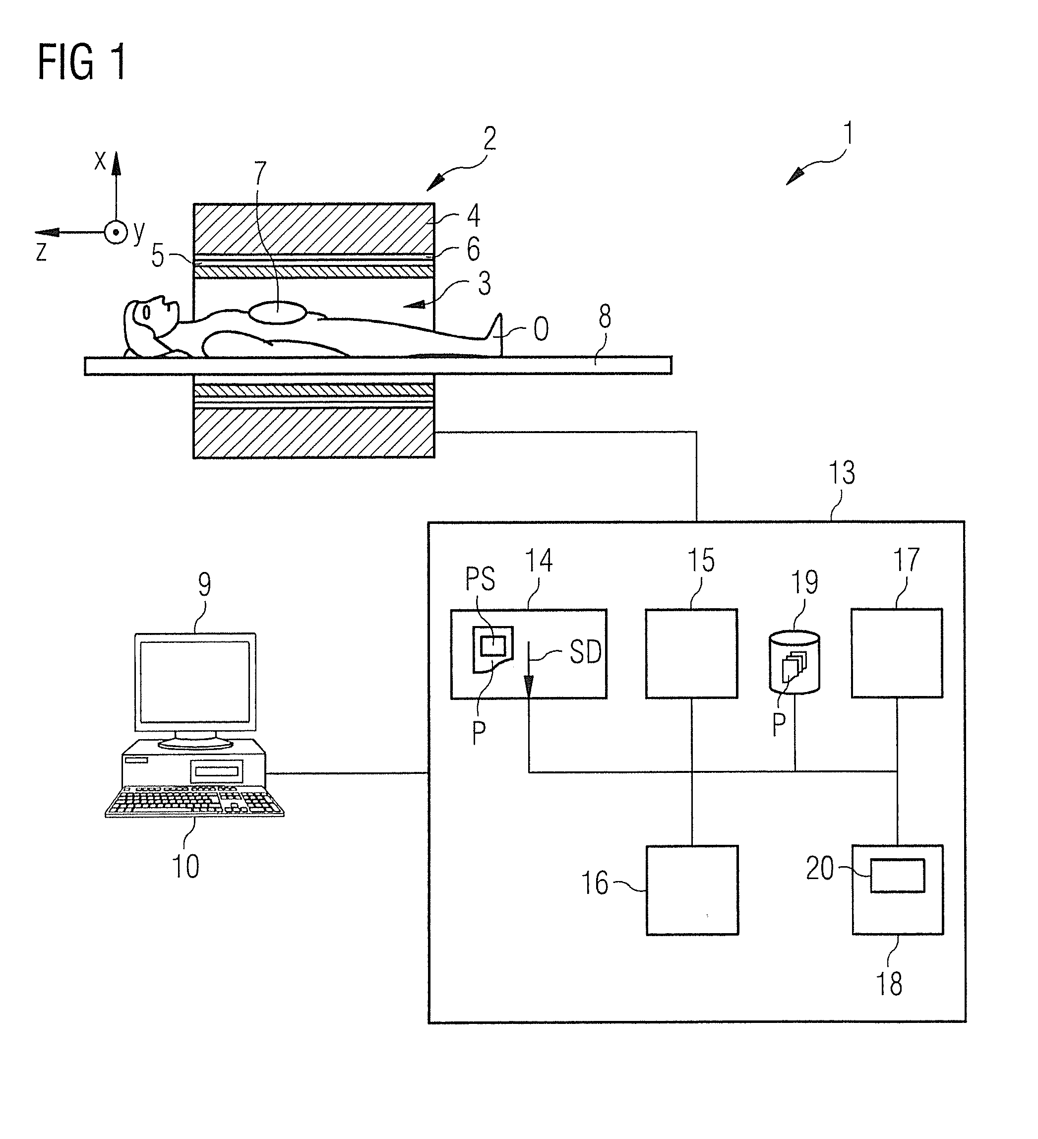
[0067]FIG. 1 shows an approximate invention-based magnetic resonance imaging system 1 (subsequently also called “MR system”). On the one hand, it comprises the actual magnetic resonance scanner 2 with an examination room 3 or tunnel, into which it is possible to insert an examination object O, or in this case a patient or test person in whose body the examination object, for example a specific organ, is located.

[0068]In conventional manner, the magnetic resonance scanner 2 is equipped with a basic field magnet system 4, a gradient system 6, as well as an RF antenna transmission system 5 and an RF antenna reception system 7. In the embodiment shown, the RF antenna transmission system 5 is a whole body coil permanently installed in the magnetic resonance scanner 2, while the RF antenna reception system 7 is composed of local coils that can be arranged on the patient or test person (symbolized in FIG. 1 only by a single local coil). Basically, it is also possible to use the whole body ...


PUM


Abstract

In a method and a control device for operating a magnetic resonance imaging system, initially, in a sequence module, multiple slices are excited in an examination object by respective spatially selective RF slice excitation pulses whereby the time between two consecutive of these RF slice excitation pulses defines a first time interval. A preparation block follows the last excitation pulse. The preparation bloc radiates at least one RF refocusing pulse designed so that, for each of the slices, one echo signal is formed. The time interval between two consecutive echo signals is equal to the first time interval. Then, a second RF refocusing pulse is emitted at a second time interval after the last echo signal formed by the preparation block. The second RF refocusing pulse is designed so that, for each of the slices, one further echo signal is formed, and the time interval of two consecutive echo signals is equal to the first time interval. Subsequently, at least one further RF refocusing pulse is emitted at a third time interval after the preceding RF refocusing pulse for producing a number of temporally separated echo signals per refocusing pulse. The third time interval is selected so that the number of echo signals per RF refocusing pulse is twice as high as the number of excited slices.

Description

BACKGROUND OF THE INVENTION[0001]1. Field of the Invention[0002]The invention concerns to a method for operating a magnetic resonance imaging (MRI) system in order to obtain magnetic resonance image data of an examination object, wherein, within a sequence module, number of slices in the examination object are excited by respective RF slice excitation pulses of a sequence of spatially selective RF slice excitation pulses, and then several RF refocusing pulses are emitted to produce, respectively, a number of temporally separate echo signals per RF refocusing pulse.[0003]Furthermore, the invention concerns a method for producing magnetic resonance image data of an examination object, wherein raw data are used that are acquired by a magnetic resonance imaging system using such a method. In addition, the invention concerns a control device for a magnetic resonance imaging system for performing such a method, as well as a magnetic resonance imaging system having such a control device.[0...

Claims


Application Information

Patent Timeline
IPC IPC(8): G01R33/565
CPCG01R33/56554G01R33/4835G01R33/5617G01R33/56341G01R33/4824
Inventor STEMMER, ALTO
Owner SIEMENS HEALTHCARE GMBH
Why Eureka
Try Eureka