Volute device for turbine

a turbine and valve device technology, applied in the direction of machines/engines, stators, liquid fuel engines, etc., can solve the problems of large impact damage, restricted regulation range for increasing the opening degree, and inability to meet the requirements, etc., to achieve good succession, low production cost, and simple structure

Inactive Publication Date: 2014-08-07
ZHU ZHIFU +7
View PDF14 Cites 14 Cited by
  • Summary
  • Abstract
  • Description
  • Claims
  • Application Information

AI Technical Summary

Benefits of technology

[0008]In view of the above-described problems, it is one objective of the invention to provide a volute device for a variable-geometry pulse turbine. The volute has a simple structure, high stability, and high efficiency in low-speed working condition, improves the work capacity of the turbine, satisfies the flow capacities of the engine at both low and high speeds, and prevents the turbocharger from overspeeding.
[0015]The opening and closing of the valve are controlled by the actuating mechanism. The allocation of the intake gas flow is controlled by regulating the opening degree of the valve, thereby achieving the co-working between the inner passage and the outer passage.
[0019]In a low speed working condition of the engine, the valve is in a closed state, the inner passage is in the work sate, and the intake gas flow discharged from the exhaust pipe only passes through the working passage. As the cross sectional area of the turbine is decreased, the intake pressure of the turbine and the available energy in the exhaust gas are increased, the work capacity of the turbine is enhanced, and the efficiency of the turbine at a low speed is improved, thereby satisfying the low-speed performance of the engine and the purpose of emission reduction.
[0022]The structure of the turbine volute of the invention is basically the same as that of a common turbocharger volute. The volute structure has a simple structure, good succession, and low production costs, and is easy and fast to achieve engineering. The intake regulation device of the invention has a simple structure, flexible controllability, and high reliability.
[0023]In summary, the volute device for the variable-geometry pulse turbine satisfies the pressurizing requirements in all working conditions. The turbocharger equipped with the volute device has non-obvious variations in external structures and low production costs. The volute device of the invention has a high market value and is suitable for engineering and industrialization.

Problems solved by technology

However, as the cross sectional area of the turbine is constant, the requirements cannot be satisfied.
However, when the engine is in a large flow working condition, the opening degree of the nozzle vane increases, and the nozzle vane is relatively close to a front edge of the turbine impeller, so that the regulation range for increasing the opening degree is restricted.
When the engine is in a small flow working condition, the opening degree of the nozzle vane is very small, the gas flow at the nozzle outlet has a high circumferential speed, and the turbine becomes an impulse turbine, thereby resulting in relatively large impact damage and poor stability.
Besides, a distance between the nozzle outlet and the impeller inlet is relatively long, and the gas flow of the annular zone therein interferences with each other, so that the flow loss is increased, and the efficiency of the turbocharger is decreased.
Furthermore, the rotary vane variable-geometry turbine has a high production cost and short service life.

Method used


Image

  • Volute device for turbine
  • Volute device for turbine
  • Volute device for turbine

Examples


example 1

[0036]As shown in FIGS. 1-2, a volute device for a variable-geometry pulse turbine comprises a volute 3 comprising an intake passage. On one end of the intake passage disposed is a gas inlet, and on the other end of the intake passage disposed is a gas outlet 4.

[0037]The intake passage comprises two groups of working passages, of which, one group is an inner passage, and the other group is an outer passage. The outer passage is disposed at one side of the inner passage.

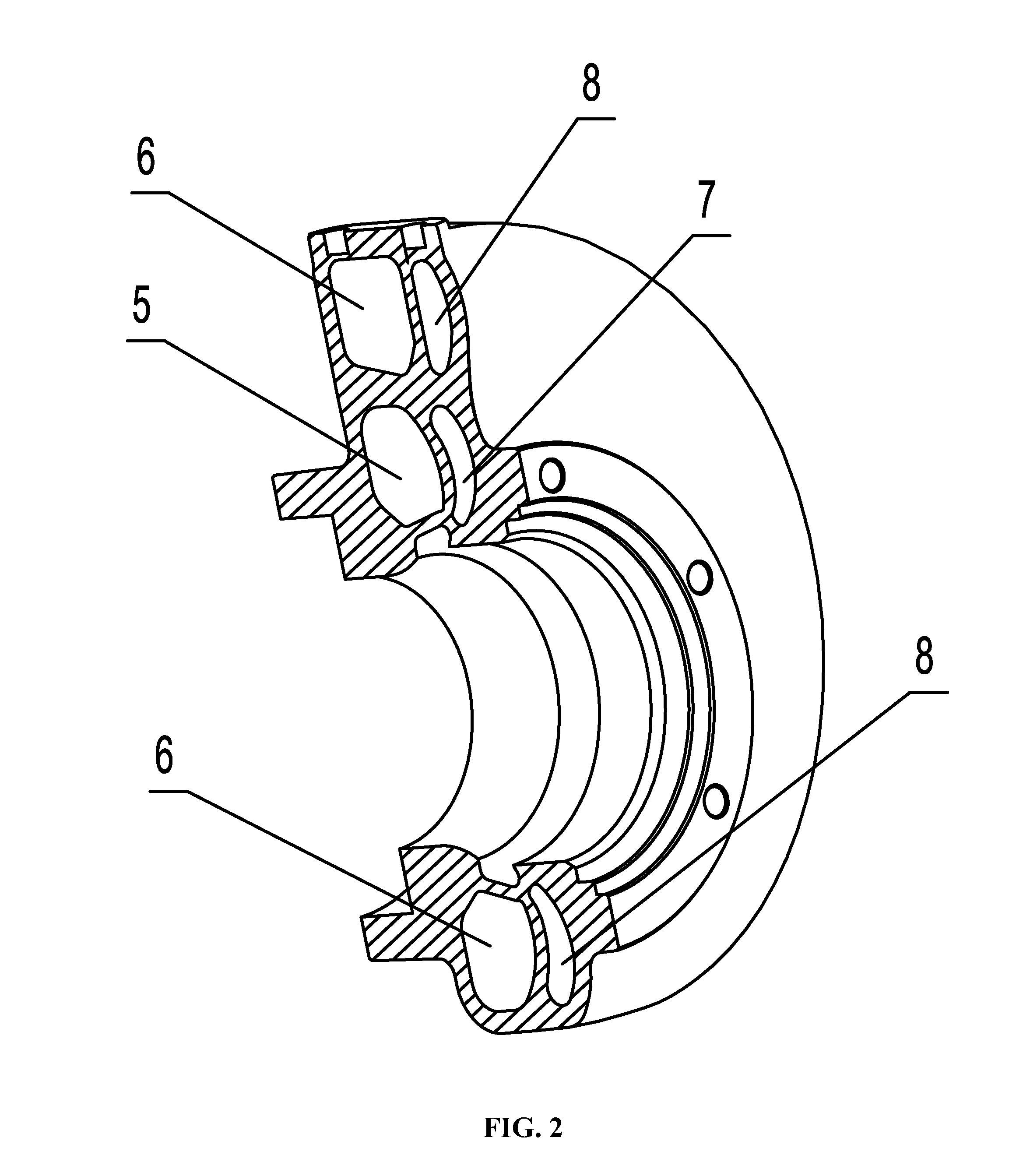
[0038]The inner passage comprises a first inner passage 5 and a second inner passage 6. The outer passage comprises a first outer passage 7 and the second outer passage 8.

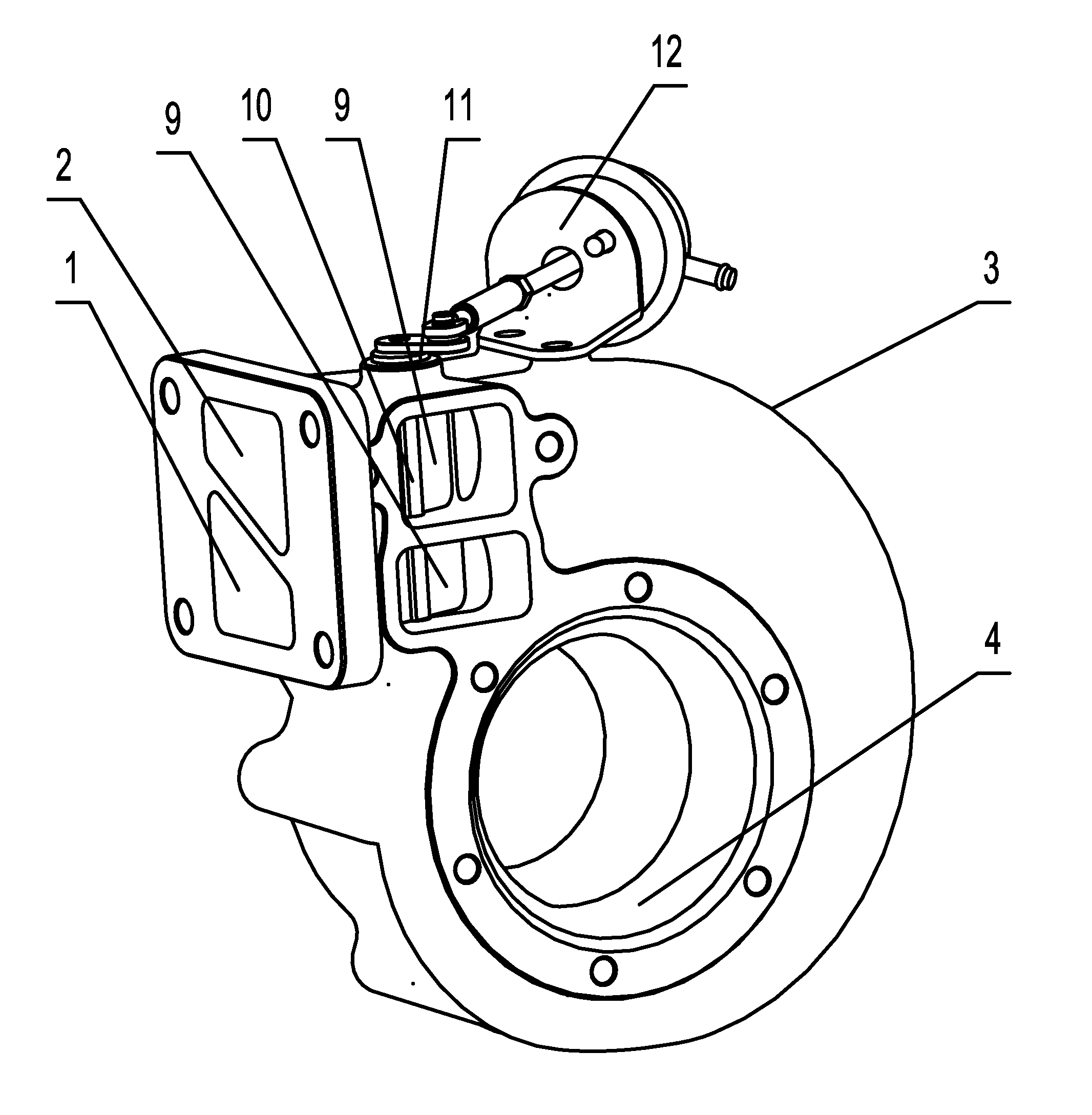
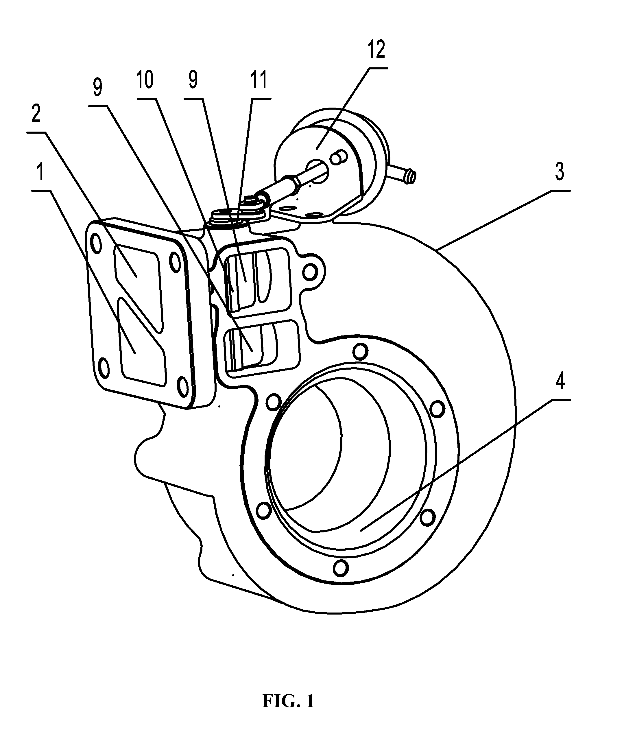
[0039]The gas inlet comprises a first gas inlet 1 and a second gas inlet 2.

[0040]The first inner passage 5 and the first outer passage 7 communicate with the first gas inlet 1 to suck gas in a semicircle of a circumference direction at between 0° and 180°.

[0041]The second inner passage 6 and the second outer passage 8 communicate with the second gas ...

example 2

[0053]As shown in FIGS. 6-7, cross sections of the first gas inlet 1 and the second gas inlet 2 are in rectangular structures and are arranged in parallel from left to right. The first gas inlet 1 and the second gas inlet 2 communicate with the exhaust manifold, respectively.

[0054]The first outer passage 7, the first inner passage 5, the second inner passage 6, and the second outer passage 8 are arranged in parallel in the volute.

[0055]As shown in FIG. 8, the exhaust manifold comprises a first exhaust outlet 14 and a second exhaust outlet 15, both of which have rectangular cross sections. The first inner passage 5 and the first outer passage 7 communicate with the corresponding first exhaust outlet 14 via the first gas inlet 1. The second inner passage 6 and the second outer passage 8 communicate with the corresponding second exhaust outlet 15 via the second gas inlet 2.

example 3

[0056]As shown in FIG. 9, the two intake regulation devices of the outer passages are disposed at both sides of the volute. The allocation of the intake gas flow is controlled by the intake regulation device according to the practical working condition of the engine.

[0057]The volute device of the invention focuses on the requirement of the engine on the variable cross section turbocharger, effectively utilizes the exhaust energy, and satisfies the pressurization requirements in both low-speed and high-speed working conditions. The volute device can be manufactured according to the casting and processing technology for conventional turbochargers.


PUM


Abstract

A volute device, including: an intake passage including an inner passage and an outer passage; a gas inlet including a first gas inlet and a second gas inlet; and a gas outlet. The gas inlet is disposed at one end of the intake passage, and the gas outlet is disposed at the other end of the intake passage. A first inner passage and a first outer passage communicate with the first gas inlet to suck gas in a semicircle of a circumference direction at between 0° and 180°. A second inner passage and a second outer passage communicate with the second gas inlet to suck gas in another semicircle of the circumference direction at between 180° and 360°.

Description

CROSS-REFERENCE TO RELATED APPLICATIONS[0001]This application is a continuation-in-part of International Patent Application No. PCT / CN2012 / 000181 with an international filing date of Feb. 15, 2012, designating the United States, now pending, and further claims priority benefits to Chinese Patent Application No. 201110297550.0 filed Oct. 8, 2011. The contents of all of the aforementioned applications, including any intervening amendments thereto, are incorporated herein by reference. Inquiries from the public to applicants or assignees concerning this document or the related applications should be directed to: Matthias Scholl P.C., Attn.: Dr. Matthias Scholl Esq., 14781 Memorial Drive, Suite 1319, Houston, Tex. 77079.BACKGROUND OF THE INVENTION[0002]1. Field of the Invention[0003]The invention relates to the field of the internal combustion engine, and more particularly to a volute device for a variable-geometry pulse turbine.[0004]2. Description of the Related Art[0005]A typical vol...

Claims


Application Information

Patent Timeline
Patent Type & Authority Applications(United States)
IPC IPC(8): F02B37/22
CPCF02B37/225F02B37/025F02B37/22F01D9/026F05D2220/40
Inventor ZHU, ZHIFULIU, YINGYUAN, DAOJUNWANG, YANXIAZHANG, JINMINGYANG, GUOQIANGGUO, MINGLIANGZHENG, WENJUAN
Owner ZHU ZHIFU
Why Eureka
Try Eureka