Thermal transfer device, temperature-control panel, and energy storage device

a technology of temperature control panel and energy storage device, which is applied in the operation mode of machines, electrochemical generators, lighting and heating apparatus, etc., and can solve problems such as permanent damage to energy stores

Inactive Publication Date: 2014-08-07
BEHR GMBH & CO KG
View PDF2 Cites 13 Cited by
  • Summary
  • Abstract
  • Description
  • Claims
  • Application Information

AI Technical Summary

Benefits of technology

[0009]As a result, it is no longer necessary to supply a temperature-control plate, for example, a cooling plate, for the temperature control of an energy store with a suitably high coolant volume flow, so that the temperature gradient in the coolant is kept low and the energy store or cells of the energy store are cooled homogeneously. If the thermal resistance of the arrangement of a plurality of functional layers along a flow direction of the coolant changes, then the coolant volume flow can be kept low, because a temperature gradient in the coolant can be compensated by the changing thermal resistance. By being able to avoid a high volume flow, low pressure losses occur in the system, so that the other components in the circuit can be dimensioned smaller; thus, for example, small, light, and cost-effective pumps can be used.
[0014]The energy store can be a battery such as, for example, a Li-ion or NiMH battery or a supercap. The energy store may comprise a plurality of battery cells. The energy store can be suitable for operating a hybrid-electric vehicle or an electric vehicle. The temperature-control plate can function as a heat source or heat sink. The temperature-control plate accordingly can be used for heating or cooling the energy store. The temperature-control plate can have one or more channels for conducting a fluid, for example, a coolant. The thermal transfer device can be arranged between a surface of the temperature-control plate and a surface of the energy store. The thermal transfer device is therefore suitable for producing a planar connection between the temperature-control plate and the energy store. The thermal transfer device can also be arranged between a surface of the temperature-control plate and a surface of a heating device. Thus, the transfer device can be arranged below the temperature-control plate, e.g., if the heating device is located below the temperature-control plate. In this regard, depending on the design, both the thermal insulation layer and the tolerance compensating layer can be arranged on the thermal transfer device side facing the energy store. The thermal insulation layer can consist solely of the insulation material. Being unevenly distributed in regard to the thermal insulation layer can mean that the material thickness of the insulation layer and therefore the entire thermal insulation layer varies over a main extension surface of the thermal insulation layer. In this way the thermal insulation layer can have different thicknesses. A material thickness of the insulation material can be equal to zero in one or more regions of the thermal insulation layer. In this case, the thermal insulation layer can comprise no insulation material in the region or regions. Therefore, a thickness of the thermal insulation layer in the region or regions can also be equal to zero. The thermal insulation layer can consist of a rigid material or a material incompressible in relation to a contact force prevailing between the energy store and the temperature-control plate. The tolerance compensating layer can consist of a different material than the thermal insulation layer. The tolerance compensating layer can have a higher thermal conductivity than the thermal insulation layer. For example, the thermal conductivity of the tolerance compensating layer can be at least four or five times as great as the thermal conductivity of the thermal insulation layer. Compressible material in relation to the tolerance compensating layer can signify that the material can deform due to a contact force prevailing between the energy store and the temperature-control plate. In this way, different thicknesses of the thermal insulation layer and tolerances of the cells in the energy store can be compensated among one another. At least part of the tolerance compensating layer can engage in the thermal insulation layer. In particular, regions of the thermal insulation layer, which have little or no insulation material, can be compensated by the compressible material of the tolerance compensating layer.
[0020]The tolerance compensating layer can have a material thickness that is between 0.3 mm and 2 mm. The tolerance compensating layer can have, for example, a material thickness that is greater than the maximum material thickness of the thermal insulation layer and smaller than four, five, or six times the maximum material thickness of the thermal insulation layer. As a result, the different thicknesses of the thermal insulation layer can be well compensated by the tolerance compensating layer.

Problems solved by technology

Temperatures above 50° C. damage the energy stores permanently.

Method used


Image

  • Thermal transfer device, temperature-control panel, and energy storage device
  • Thermal transfer device, temperature-control panel, and energy storage device
  • Thermal transfer device, temperature-control panel, and energy storage device

Examples


Embodiment Construction

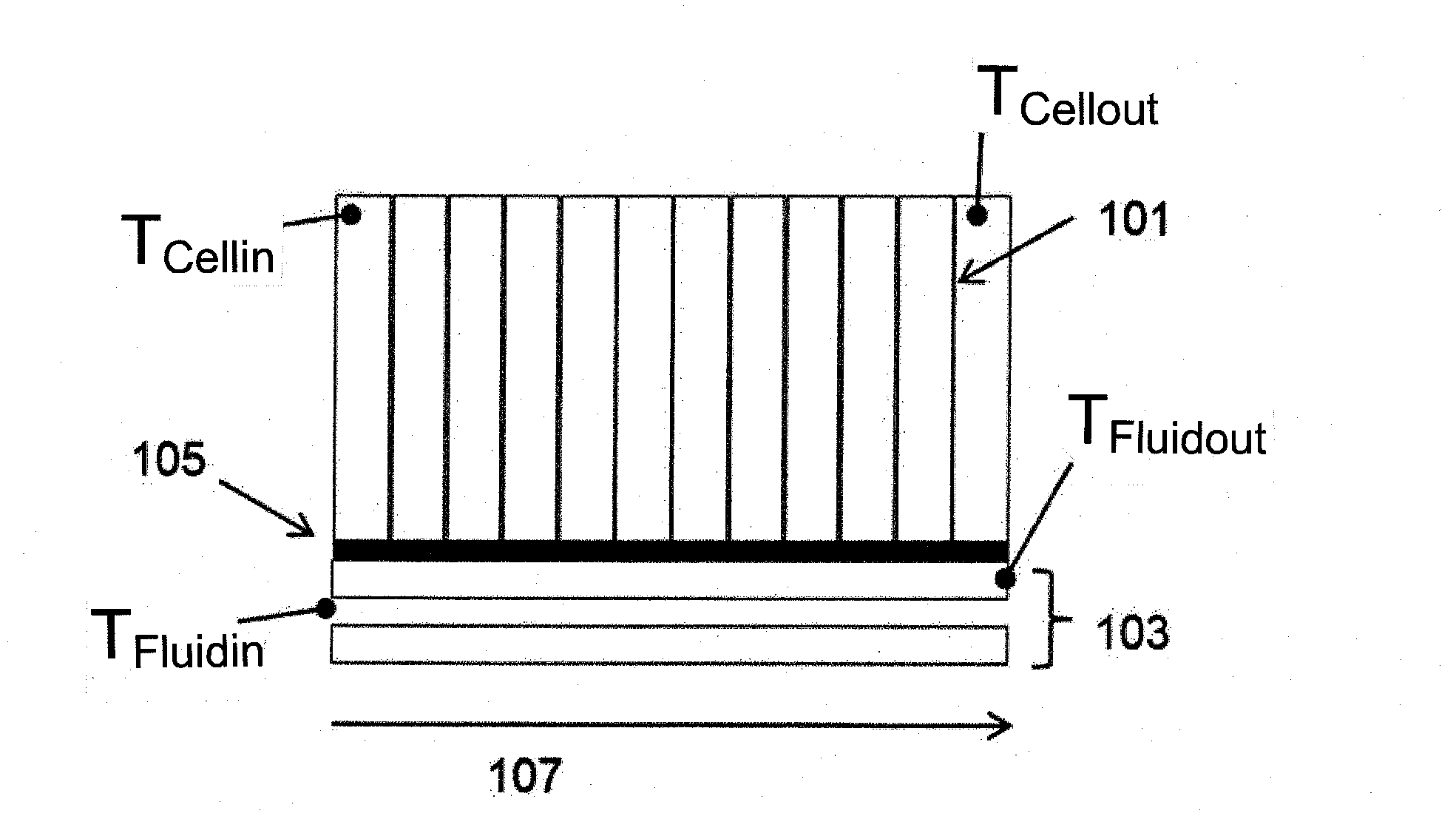
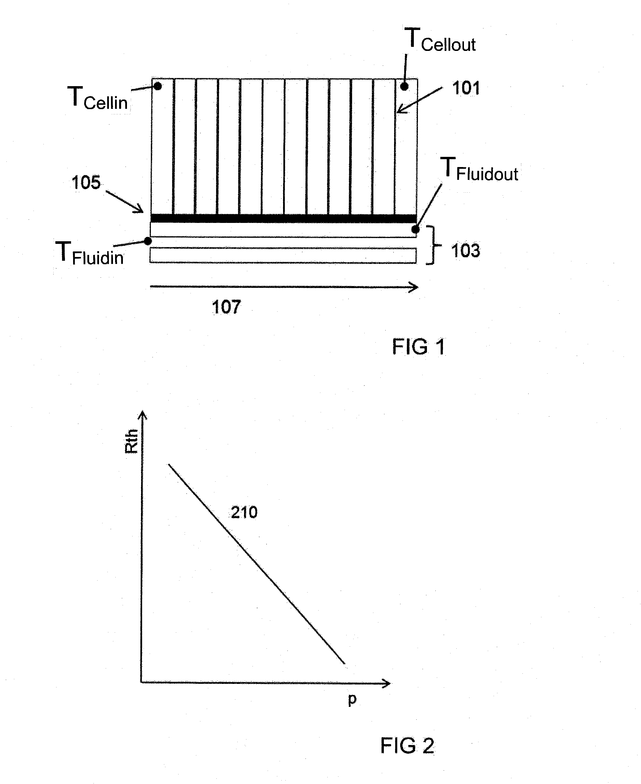
[0041]FIG. 1 shows a cross-sectional illustration of an energy storage device according to an exemplary embodiment of the present invention. The energy storage device has an energy store in the form of battery cells 101, a temperature-control plate in the form of a cooling plate 103 with at least one flow channel, and a thermal transfer device 105, arranged between battery cells 101 and cooling plate 103, in the form of functional layers.

[0042]Battery cells 101 are arranged next to one another on a surface of an outer layer of the functional layers of transfer device 105. During operation of the energy storage device, a fluid can flow through the flow channel of cooling plate 103. A flow path length 107 or flow direction of the fluid between an inlet and an outlet of the flow channel is indicated by an arrow. The fluid has a temperature TFluidin at the inlet. The fluid has a temperature TFluidout at the outlet. A battery cell 101 located closest to the inlet has a temperature TCelli...


PUM

PropertyMeasurementUnit
thicknessaaaaaaaaaa
thicknessaaaaaaaaaa
thicknessaaaaaaaaaa

Abstract

A thermal transfer device for generating a thermal transfer between an energy store and a temperature-control panel for the temperature-control of the energy store. The thermal transfer device has a thermal insulation layer made of an unevenly distributed insulation material and a tolerance compensating layer made of a compressible material for compensating different material strengths of the thermal insulation layer.

Description

[0001]This nonprovisional application is a continuation of International Application No. PCT / EP2012 / 069592, which was filed on Oct. 4, 2012, and which claims priority to German Patent Application No. DE 10 2011 084 002.8, which was filed in Germany on Oct. 4, 2011, and which are both herein incorporated by reference.BACKGROUND OF THE INVENTION[0002]1. Field of the Invention[0003]The present invention relates to a thermal transfer device for producing a thermal transfer between an energy store and a temperature-control plate for the temperature control of the energy store, to a temperature-control plate, and to an energy storage device.[0004]2. Description of the Background Art[0005]High-performance energy stores such as, for example, Li-ion or NiMH batteries or supercaps are used in modern hybrid electric vehicles (HEV) or electric vehicles (EV). Heating occurs in these during rapid charging and discharging due to resistances within and outside the cells. Temperatures above 50° C. d...

Claims


Application Information

Patent Timeline
Patent Type & Authority Applications(United States)
IPC IPC(8): H01G11/18H01M10/653
CPCH01M10/504H01G11/18H01M10/613H01M10/615H01M10/617H01M10/6556H01M10/6568H01M10/653Y02E60/10
Inventor HIRSCH, STEFANSCHMID, CAROLINESTRIPF, MATTHIASWIEBELT, ACHIM
Owner BEHR GMBH & CO KG
Why Eureka
Try Eureka