
Power transmitting device, vehicle, and power transfer system

a power transmission device and power transfer technology, applied in the direction of engine-driven generators, rail devices, transportation and packaging, etc., can solve the problems of ferrite core heating to a high temperature, wires may become noise generators, etc., and achieve the effect of suppressing an increase in the temperature of a certain portion and reducing noise radiated

Inactive Publication Date: 2014-08-14
TOYOTA JIDOSHA KK
View PDF0 Cites 12 Cited by
  • Summary
  • Abstract
  • Description
  • Claims
  • Application Information

AI Technical Summary

Benefits of technology

The invention is about a device and system for transmitting power. It reduces noise and keeps the temperature of certain parts down, even when a coaxial cable is connected to a transmitter. This means that it minimizes interference and keeps things cool, improving the efficiency of power transfer.

Problems solved by technology

As a result, an, electromagnetic wave is formed around the wiring line and the wiring line may become a noise generating source.
When common mode current flows, an electromagnetic wave is radiated from the coaxial cable, and becomes a cause of noise.
On the other hand, when high frequency AC flows through the balun, there is a problem that the ferrite core is heated to a high temperature.

Method used


Image

  • Power transmitting device, vehicle, and power transfer system
  • Power transmitting device, vehicle, and power transfer system
  • Power transmitting device, vehicle, and power transfer system

Examples


Embodiment Construction

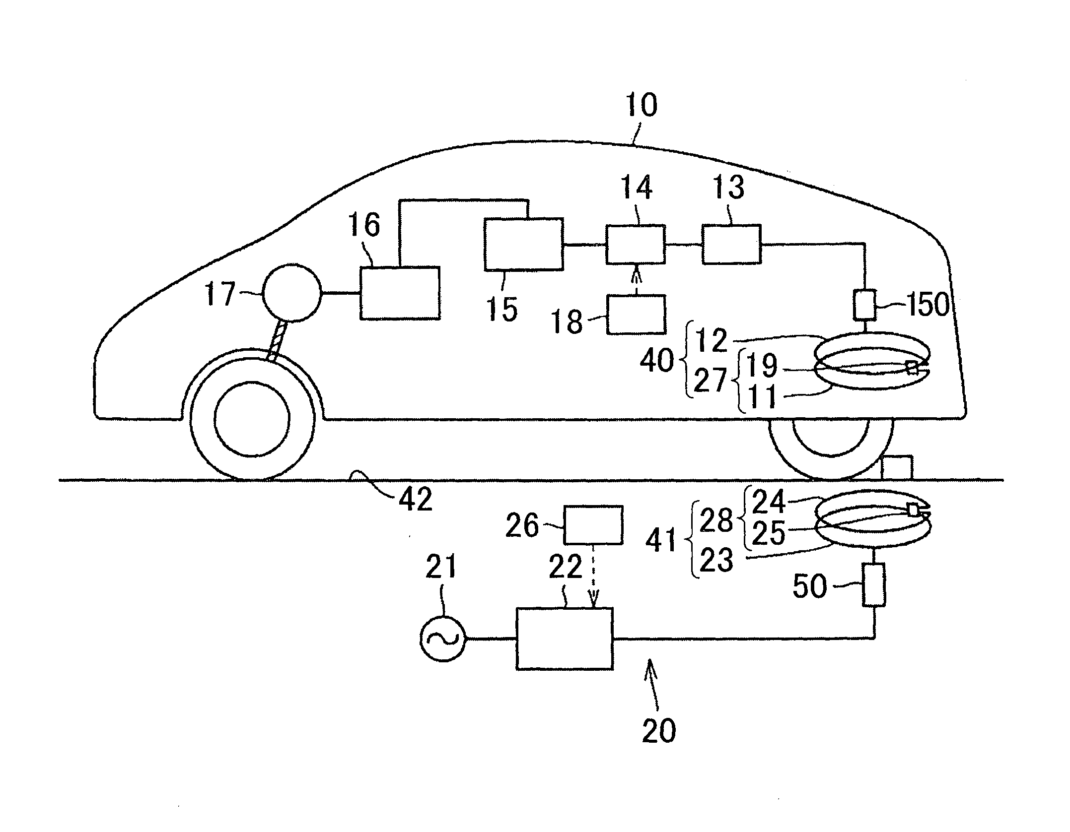
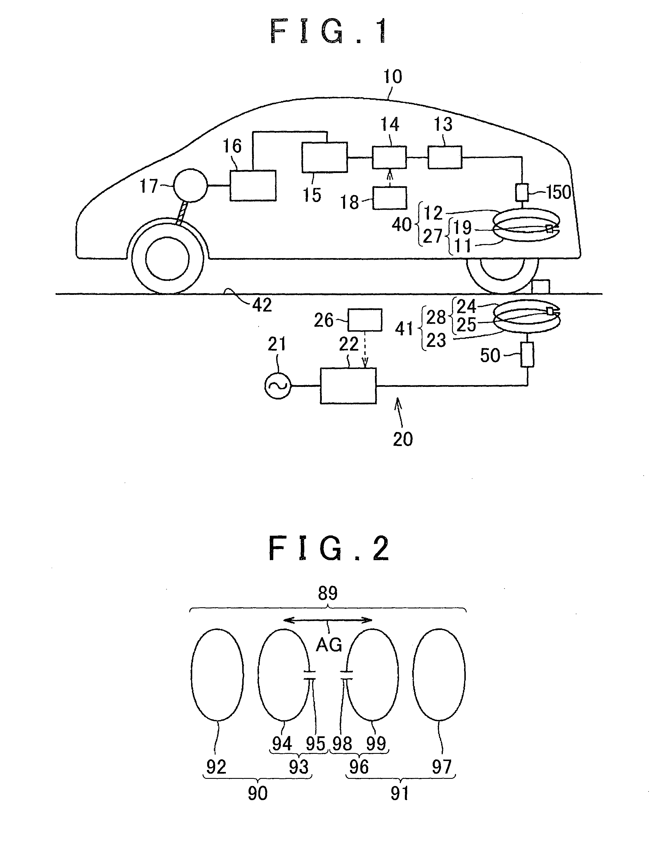
[0051]A power receiving device, a power transmitting device and a power transfer system that includes the power transmitting device and the power receiving device according to an embodiment of the invention will be described with reference to FIG. 1 to FIG. 13. FIG. 1 is a schematic view that schematically shows the power receiving device, the power transmitting device and the power transfer system according to the present embodiment.

[0052]The power transfer system according to the present embodiment includes an electromotive vehicle 10 and an external power supply device 20. The electromotive vehicle 10 includes the power receiving device 40. The external power supply device 20 includes the power transmitting device 41. When the electromotive vehicle 10 is stopped at a predetermined position of a parking space 42 in which the power transmitting device 41 is provided, the power receiving device 40 of the electromotive vehicle 10 receives electric power from the power transmitting de...


PUM

PropertyMeasurementUnit
electric poweraaaaaaaaaa
currentaaaaaaaaaa
shapeaaaaaaaaaa

Abstract

A power transmitting device includes: a power transmitting portion that contactlessly transmits electric power to a power receiving portion spaced apart from the power transmitting portion; a first coil unit that is spaced apart from the power transmitting portion and that supplies electric power to the power transmitting portion; and a supply cable that is connected to the first coil unit and that supplies electric power from a power supply to the first coil unit. The first coil unit includes a first coil connected to the supply cable and a second coil connected to the first coil, and the first coil is arranged around, the power transmitting portion, converts unbalanced current, supplied from the power supply, to balanced current and supplies the balanced current to the second coil.

Description

BACKGROUND OF THE INVENTION[0001]1. Field of the Invention[0002]The invention relates to a power transmitting device, a vehicle and a power transfer system.[0003]2. Description of Related Art[0004]In recent years, hybrid vehicles, electric vehicles, and the like, that drive driving wheels with the use of electric power from a battery, or the like, become a focus of attention in consideration of an environment.[0005]Particularly, in the above-described electromotive vehicles equipped with a battery, wireless charging through which the battery is contactlessly chargeable without using a plug, or the like, becomes a focus of attention. Various charging systems have been suggested recently, and, particularly, a technique for contactlessly transferring electric power with the use of a resonance phenomenon is put in the spotlight.[0006]For example, a wireless power transfer system described in Japanese Patent Application Publication No. 2010-73976 (JP 2010-73976 A) is one of wireless powe...

Claims


Application Information

Patent Timeline
Patent Type & Authority Applications(United States)
IPC IPC(8): B60L11/18H04B5/00B60L50/16B60M7/00H01F38/14H02J7/00
CPCH04B5/0037B60L11/182H01F38/14B60L2270/147B60L2210/10B60L2210/40H01F27/28H01F27/38Y02T90/14Y02T10/70B60L50/16B60L53/38B60L53/36B60L53/34B60L53/126H02J2310/48Y02T10/72Y02T10/7072Y02T90/12H02J50/502H02J50/12H02J7/00034H04B5/79H04B5/26H04B5/263B60L53/12H02J7/00
Inventor ICHIKAWA, SHINJINAKAMURA, TORUISHIDA, MASAYAWATANABE, TOSHIAKIAMANO, YASUSHI
Owner TOYOTA JIDOSHA KK
Learn More