Method for Suppressing Circulating Current in Modular Multilevel Converter for High Voltage Direct-Current Transmission

Active Publication Date: 2014-08-14
KOREA ELECTROTECH RES INST
View PDF1 Cites 63 Cited by
  • Summary
  • Abstract
  • Description
  • Claims
  • Application Information

AI Technical Summary

Benefits of technology

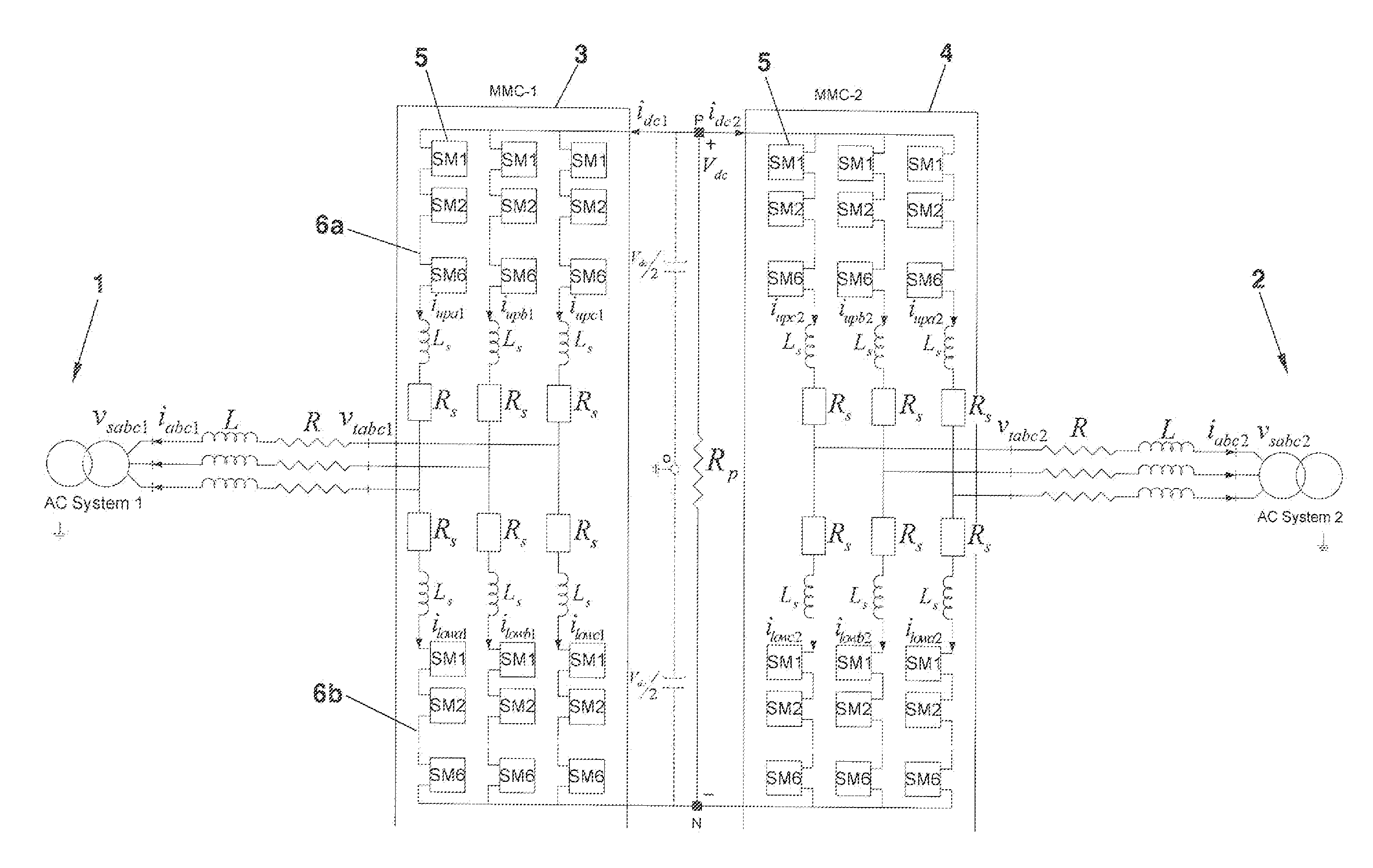
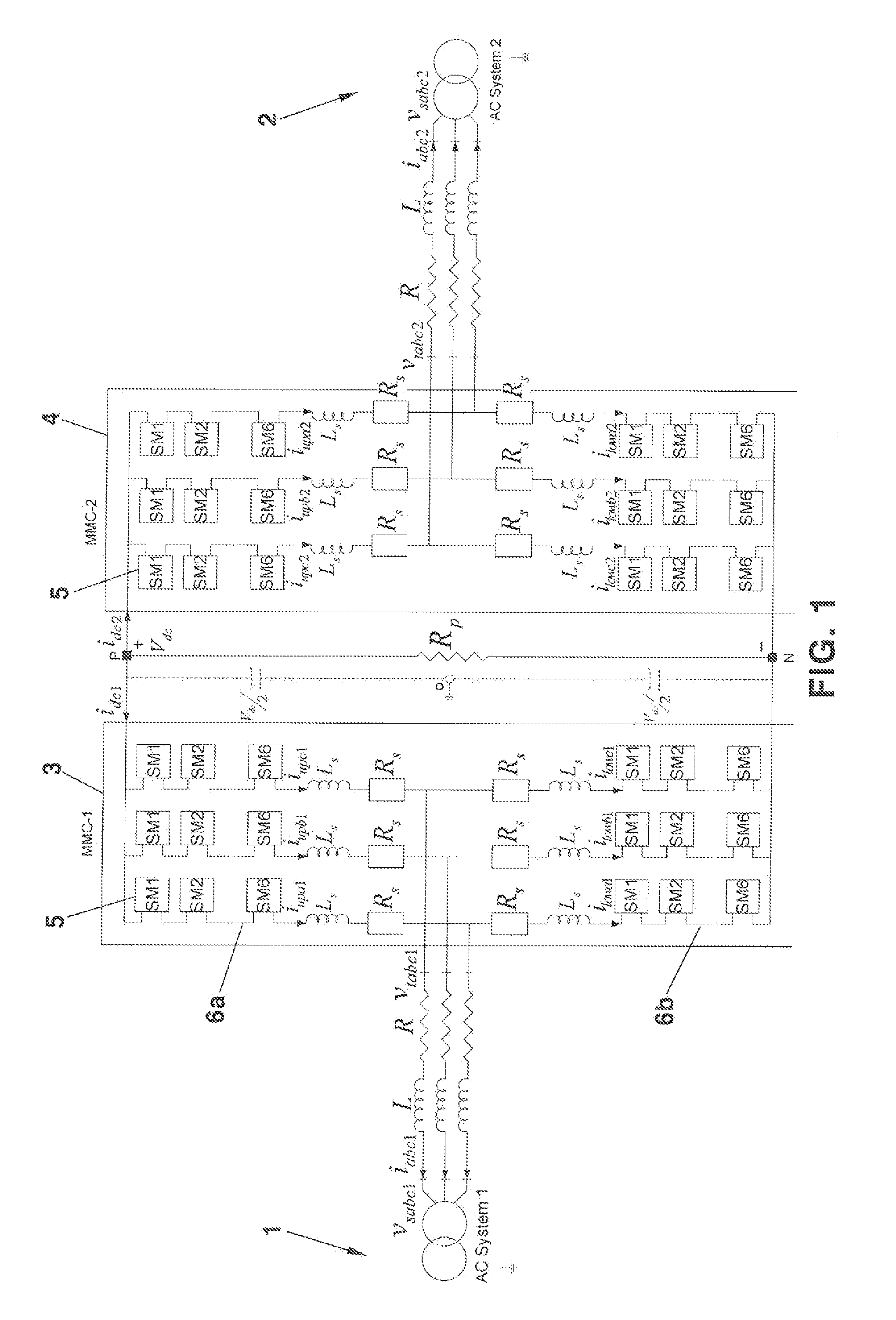
[0028]The present invention provides a method for suppressing a circulating current in a modular multi-level converter for high voltage direction-current transmission, which can save the manufacturing cost by completely removing an AC component of a circulating current shown in a modular multi-level converter an

Problems solved by technology

However, the HVDC converter with the modular multilevel converter has limitations that are not present in the current-type converter.
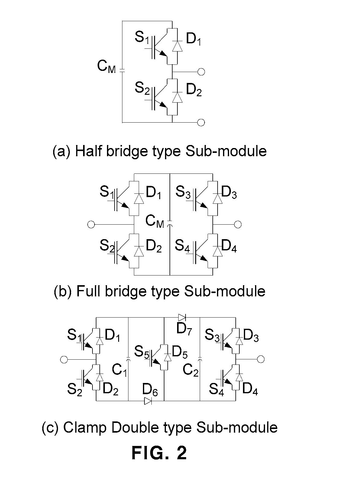
In other words, the capacity voltage in the sub-modules is not uniform.
This circulating current flows only in the multilevel converter, and is known to be unnecessary for transmitting electrical energy.
As described above, if the circulating current increases in the HVDC multilevel converter, a current of a reactive component that does not act in the energy conversion additionally flows, and thus the current specifications of the components (IGBT, capacitor, SCR, and fast switch) used in the sub-modules become higher, re

Method used


Image

  • Method for Suppressing Circulating Current in Modular Multilevel Converter for High Voltage Direct-Current Transmission
  • Method for Suppressing Circulating Current in Modular Multilevel Converter for High Voltage Direct-Current Transmission
  • Method for Suppressing Circulating Current in Modular Multilevel Converter for High Voltage Direct-Current Transmission

Examples


Embodiment Construction

[0085]Hereinafter reference will now be made in detail to various embodiments of the present invention, examples of which are illustrated in the accompanying drawings and described below. While the invention will be described in conjunction with exemplary embodiments, it will be understood that present description is not intended to limit the invention to those exemplary embodiments. On the contrary, the invention is intended to cover not only the exemplary embodiments, but also various alternatives, modifications, equivalents and other embodiments, which may be included within the spirit and scope of the invention as defined by the appended claims.

[0086]The above and other features of the invention are discussed infra.

[0087]Hereinafter, exemplary embodiments of the present invention will be described in detail with reference to the accompanying drawings so that those skilled in the art can easily carry out the present invention.

[0088]The present invention relates to a method of sup...


PUM


Abstract

Provided is a method for suppressing a circulating current in a modular multi-level converter for a high voltage direction-current (HVDC) transmission system. The HVDC transmission system converts an alternating current (AC) into a direct current (DC) and vice versa, transmits energy using a DC cable, and including a modular multilevel converter generating a high voltage source by stacking a plurality of sub-modules in series. In the circulating current suppression method, a circulating current (idiffj; j=a,b,c) of a,b,c phase in an abc 3-phase stationary reference frame, a DC current (idc) flowing in a DC cable, a current reference value (i*dc) of a DC component that needs to flow in the DC cable are inputted. The circulating current (idiffj) of the a,b,c phase is controlled to become zero. A compensation value (V*diffj) for suppressing a harmonic component of the circulating current is outputted.

Description

CROSS-REFERENCE TO RELATED APPLICATION[0001]This application claims under 35 U.S.C. §119(a) the benefit of Korean Patent Application No. 10-2013-0015280 filed Feb. 13, 2013, the entire contents of which are incorporated herein by reference.BACKGROUND[0002](a) Technical Field[0003]The present invention relates to a method for suppressing a circulating current in a modular multi-level converter for high voltage direction-current transmission. More specifically, it relates to a method for suppressing a circulating current in a modular multi-level converter for high voltage direction-current transmission, which can further improve a current flowing in a direct current line end while further improving the circulating current suppression characteristics.[0004](b) Background Art[0005]Generally, the High Voltage Direct-Current (HVDC) transmission has advantages such as the long distance transmission, the asynchronous system connection, the submarine cable use, and the possible power control...

Claims


Application Information

Patent Timeline
IPC IPC(8): H02M1/12H02M5/458
CPCH02M5/4585H02M1/12H02M1/15H02J3/36H02M7/483Y02E60/60Y02B70/10H02M7/4835
Inventor PARK, JUNG WOOKANG, DAE WOOKKIM, JONG HYUNYOO, DONG WOOKMOON, JI WOOKWON, JIN SOOKIM, CHUN SUNGBAE, DEUK WOO
Owner KOREA ELECTROTECH RES INST
Why Eureka
Try Eureka