Optical laminate

a technology of optical laminate and hard coating layer, which is applied in the field of optical laminate, can solve the problems of poor adhesiveness of the base material film with a hard coating layer, poor moisture permeability of the optical laminate, and deterioration of the optical characteristics of the polarizer, etc., and achieves excellent adhesiveness, suppressed interference unevenness, and low moisture permeability

Active Publication Date: 2014-08-14
NITTO DENKO CORP
View PDF6 Cites 23 Cited by
  • Summary
  • Abstract
  • Description
  • Claims
  • Application Information

AI Technical Summary

Benefits of technology

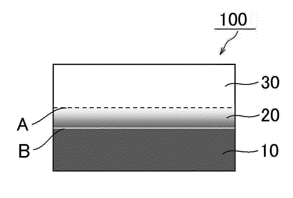
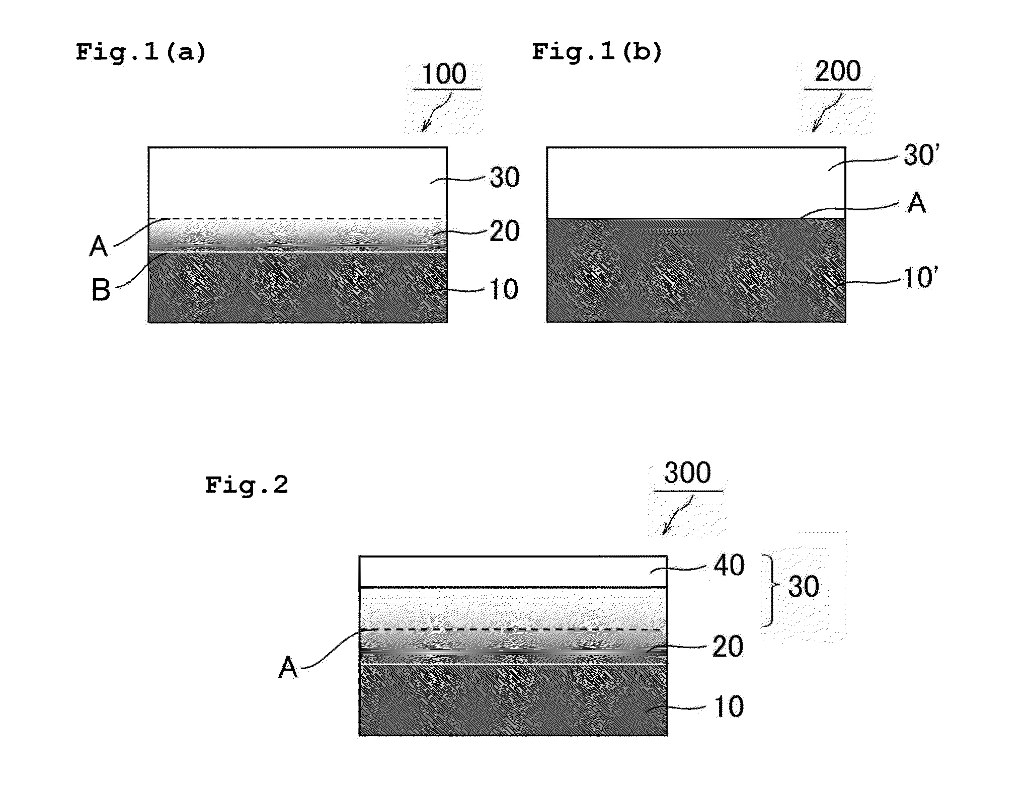
[0025]According to the present invention, the following optical laminate is provided. The optical laminate includes a base material layer and a hard coat layer formed by applying a composition for forming a hard coat layer onto a (meth)acrylic resin film (base material film), and a penetration layer formed by the penetration of the composition for forming a hard coat layer into the (meth)acrylic resin film. Accordingly, despite the fact that the optical laminate uses, as its base material film, the (meth)acrylic resin film having low moisture permeability, the optical laminate is excellent in adhesiveness between the base mat

Problems solved by technology

Accordingly, when the optical laminate including such base material film is used in the LCD, the following problem arises.
Under high temperature and high humidity, moisture permeates the optical laminate to deteriorate the optical characteristics of a polarizer.
However, such cycloolefin base material film involves the following problem.
The base material film has poor adhesiveness with a hard coat layer.
In addition, the following problem arises.
The base material film does not

Method used


Image

  • Optical laminate
  • Optical laminate
  • Optical laminate

Examples


production example 1

Production of Base Material Film A

[0133]100 Parts by weight of an imidized MS resin described in Production Example 1 of Japanese Patent Application Laid-open No. 2010-284840 and 0.62 part by weight of a triazine-based UV absorbing agent (manufactured by ADEKA CORPORATION, trade name: T-712) were mixed with a biaxial kneader at 220° C. to produce a resin pellet. The resultant resin pellet was dried at 100.5 kPa and 100° C. for 12 hours, and was then extruded from the T-die of a uniaxial extruder at a die temperature of 270° C. to be formed into a film shape (having a thickness of 160 μm). Further, the film was stretched in its conveyance direction under an atmosphere at 150° C. (to have a thickness of 80 μm). Next, the film was stretched in a direction perpendicular to the film conveyance direction under an atmosphere at 150° C. to provide a base material film A ((meth)acrylic resin film) having a thickness of 40 μm. The resultant base material film A had a transmittance for light h...

example 1

[0134]100 Parts of a UV-curable resin (manufactured by DIC Corporation, trade name: UNIDIC 17-806, solid content: 80%, solvent: butyl acetate) containing 13 parts of isocyanuric acid triacrylate, parts of pentaerythritol triacrylate, 62 parts of dipentaerythritol hexaacrylate, and 9 parts of isophorone diisocyanate polyurethane, 5 parts of a leveling agent (manufactured by DIC Corporation, trade name: GRANDIC PC-4100), and 3 parts of a photopolymerization initiator (manufactured by Ciba Japan, trade name: IRGACURE 907) were mixed, and then the mixture was diluted with methyl isobutyl ketone so that a solid content concentration became 50%. Thus, a composition for forming a hard coat layer was prepared.

[0135]The resultant composition for forming a hard coat layer was applied onto the base material film A obtained in Production Example 1 to form an application layer, and then the application layer was heated at 110° C. for 1 minute. The application layer after the heating was cured by...

example 2

[0136]An optical laminate was obtained in the same manner as in Example 1 except that the heating temperature of the application layer was set to 120° C. The optical laminate was subjected to the evaluations in the sections (2) to (5). Table 1 below shows the results.


PUM

PropertyMeasurementUnit
Temperatureaaaaaaaaaa
Lengthaaaaaaaaaa

Abstract

There is provided an optical laminate excellent in adhesiveness between a (meth)acrylic resin film (base material film) having low moisture permeability and a UV absorbing ability and a hard coat layer, and has suppressed interference unevenness. An optical laminate according to an embodiment of the present invention includes: a base material layer formed of a (meth)acrylic resin film; a hard coat layer formed by applying a composition for forming a hard coat layer to the (meth)acrylic resin film; and a penetration layer formed through penetration of the composition for forming a hard coat layer into the (meth)acrylic resin film, the penetration layer being placed between the base material layer and the hard coat layer, wherein the penetration layer has a thickness of 1.2 μm or more.

Description

TECHNICAL FIELD[0001]The present invention relates to an optical laminate.BACKGROUND ART[0002]When the surface of an image display apparatus such as a liquid crystal display (LCD), a cathode-ray tube display apparatus (CRT), a plasma display (PDP), or an electroluminescence display (ELD) is flawed by external contact, the visibility of a display image may reduce. Accordingly, an optical laminate including a base material film and a hard coat layer has been used for the purpose of protecting the surface of the image display apparatus. Triacetylcellulose (TAC) has been representatively used in the base material film of the optical laminate. However, the base material film formed of TAC has a high moisture permeability. Accordingly, when the optical laminate including such base material film is used in the LCD, the following problem arises. Under high temperature and high humidity, moisture permeates the optical laminate to deteriorate the optical characteristics of a polarizer. In rec...

Claims


Application Information

Patent Timeline
IPC IPC(8): G02B1/04B32B27/30G02B1/10G02B1/11G02B1/14G02B5/02G02B5/30G02F1/1335
CPCG02B1/04G02B5/3033G02F2201/50G02F2202/28Y10T428/265Y10T428/24355G02B1/14C08L33/08C08L33/10
Inventor SHIBATA, SHUSAKUTAKADA, KATSUNORITAKEMOTO, HIROYUKI
Owner NITTO DENKO CORP
Why Eureka
Try Eureka