
Hand-held power tool and method for operating the hand-held power tool

a technology of hand-held power tools and hand-held tools, which is applied in the direction of manufacturing tools, portable power-driven tools, metal-working machine components, etc., can solve the problems of unsuitable auxiliary handles, undesirable twisting of the hand of the user holding the tool, and injury of the particular user, so as to increase the safety of machine tools

Inactive Publication Date: 2014-08-21
ROBERT BOSCH GMBH
View PDF10 Cites 47 Cited by
  • Summary
  • Abstract
  • Description
  • Claims
  • Application Information

AI Technical Summary

Benefits of technology

The patent aims to improve the safety of machine tools with mountable auxiliary handles. The method and electric hand-held power tool described in the patent make use of a threshold value to evaluate the instantaneous operating state of the machine tool, based on the detection of the auxiliary handle and the user's grip on it. This allows for the activation of protective functions only when the user is not holding the machine tool with both hands, reducing the risk of accidental activation while safely handling the machine tool. Additionally, the method recognizes the occurrence of a kickback event and reduces or completely switches off the power of the motor to prevent hazardous torque peaks and potential injury to the user.

Problems solved by technology

Due to the high torque which such a tool may generate during operation, use of the tool without an appropriate auxiliary handle represents a relatively high safety risk for the particular user.
Thus, very high torque peaks may occur in drills, screwdrivers, or similar rotating machine tools in certain operating states, which may result in undesirable twisting of the hand of the user holding the tool.
In particular, the situation may thus be effectively avoided that if an auxiliary handle is not present on the housing or in the case that the auxiliary handle is not gripped or is not correctly gripped by the user, the operation of the machine tool results in an injury to the particular user.
In particular for high-power machine tools or at high rotational speeds, such kickback events may result in hazardous torque peaks.

Method used


Image

  • Hand-held power tool and method for operating the hand-held power tool
  • Hand-held power tool and method for operating the hand-held power tool
  • Hand-held power tool and method for operating the hand-held power tool

Examples


Embodiment Construction

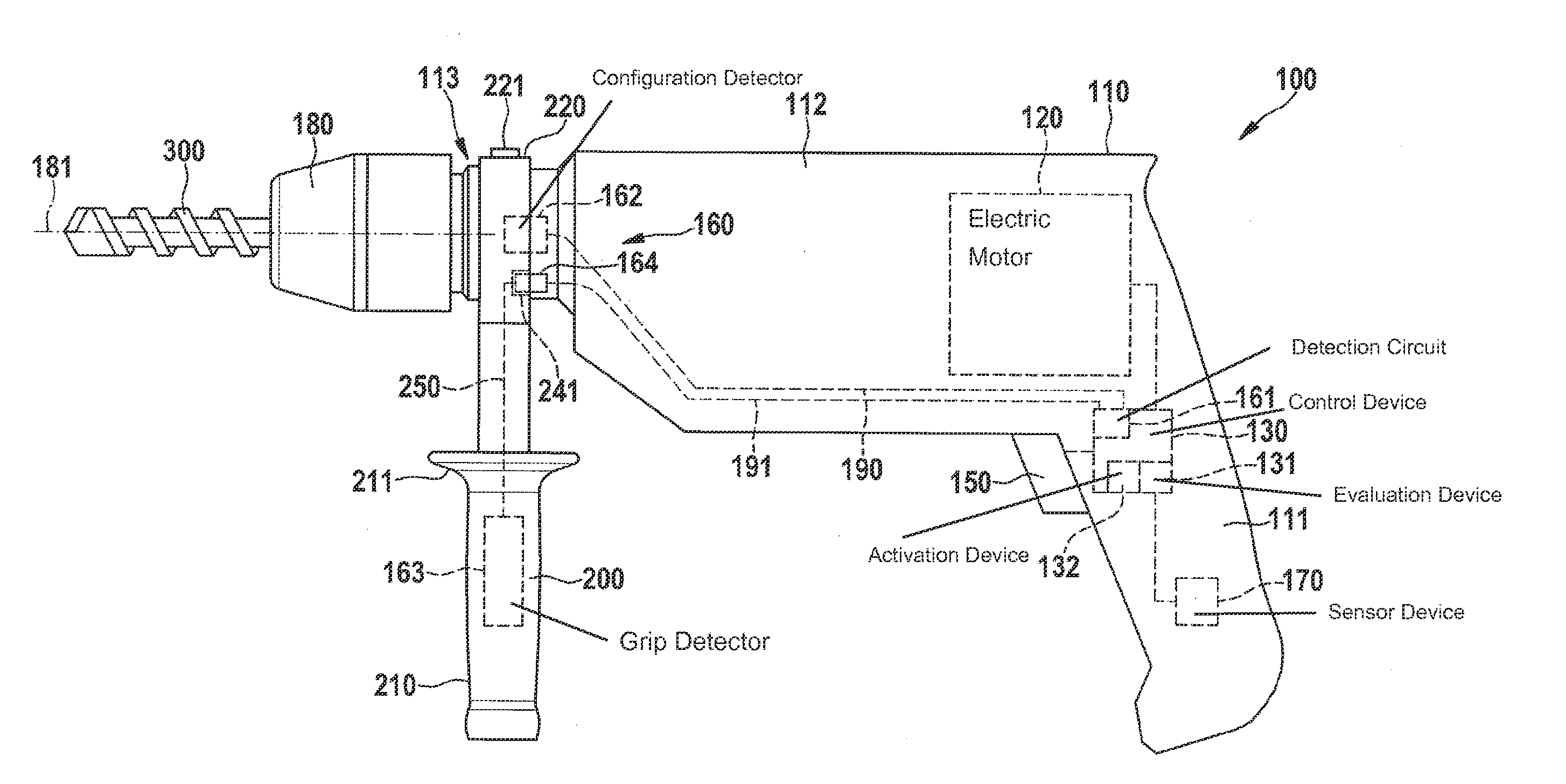
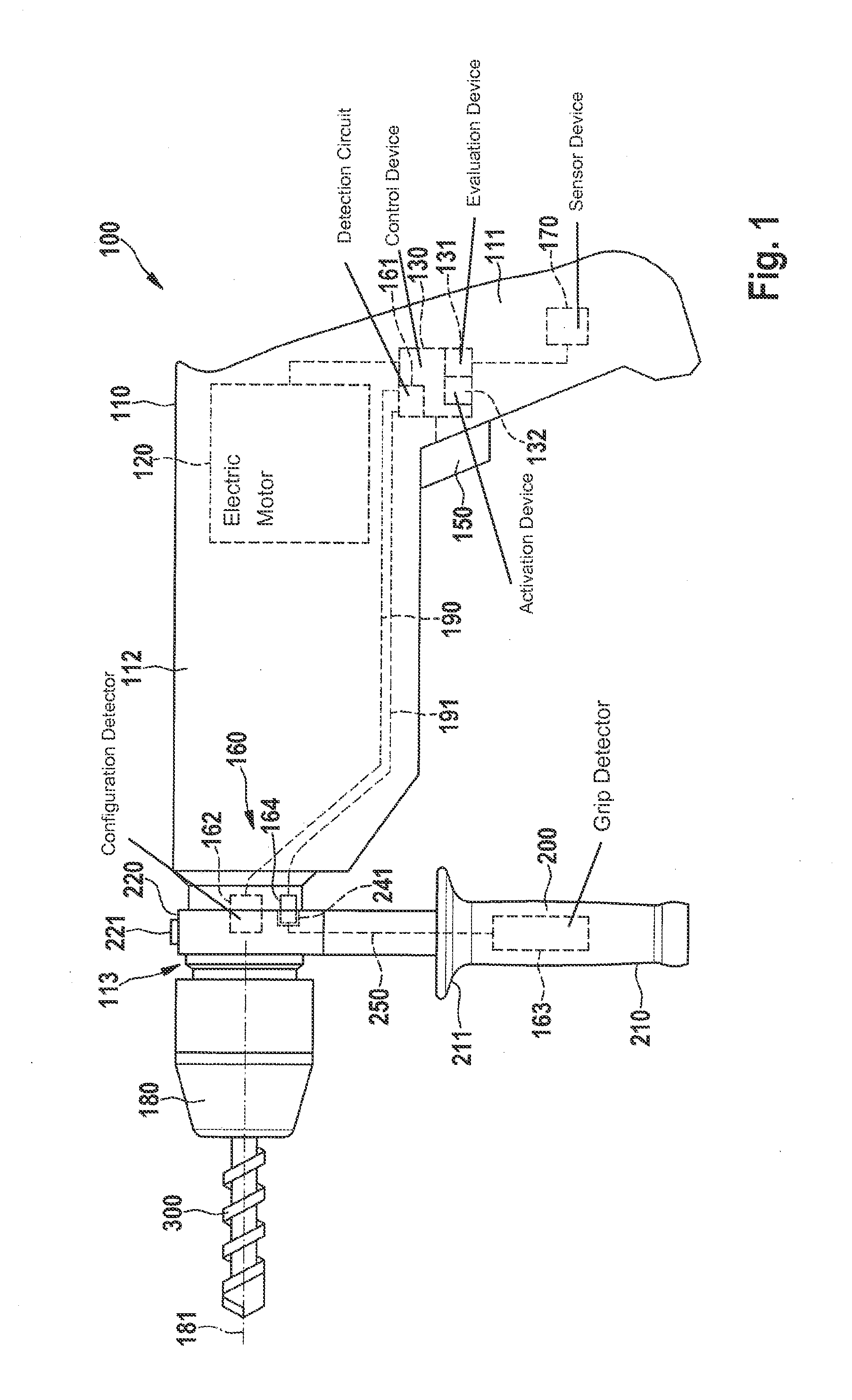
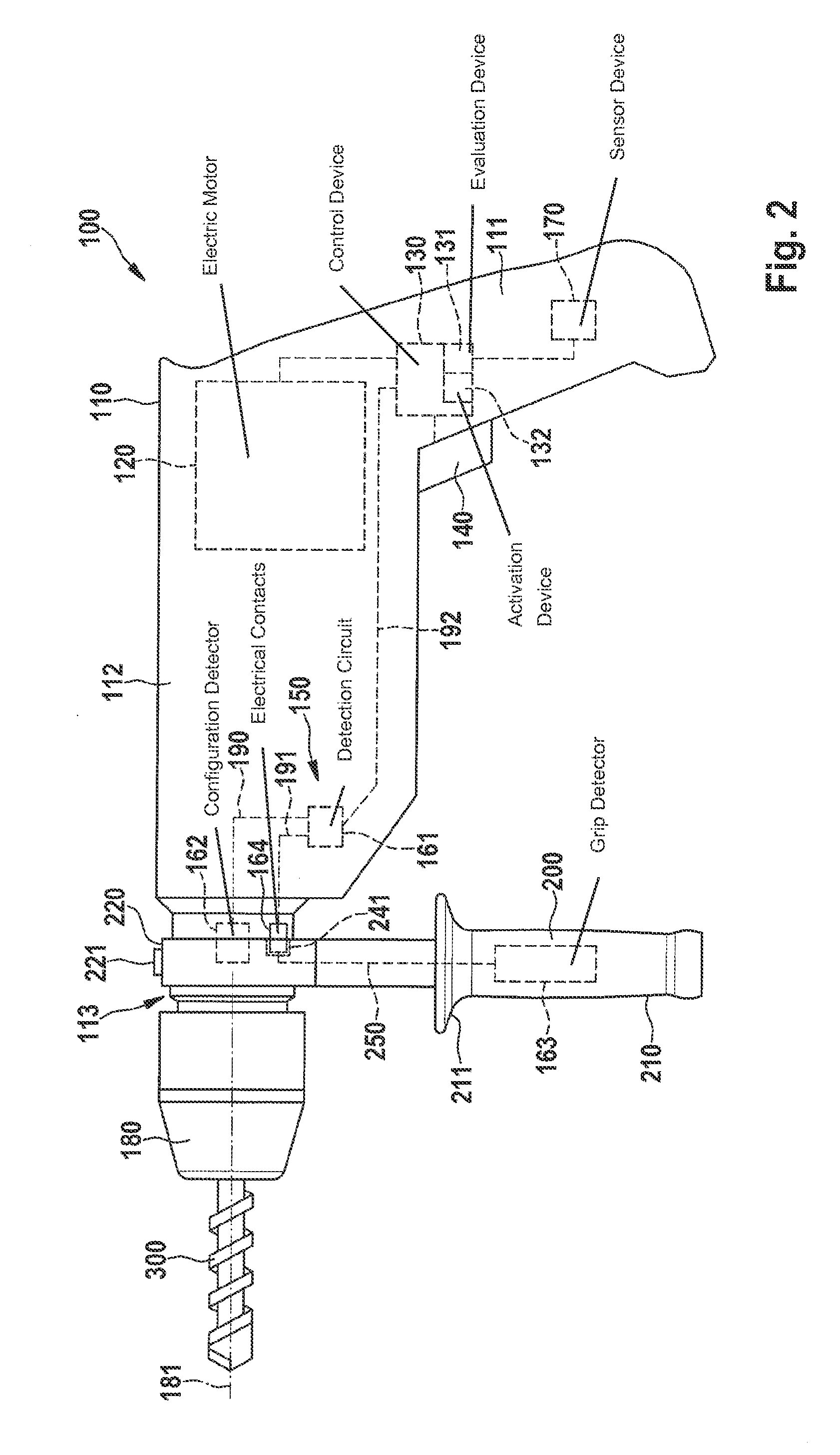
[0018]FIG. 1 shows a schematic illustration of an electric hand-held power tool 100 which is designed, for example, in the form of a drill, hammer drill, power screwdriver, or a similar device. Machine tool 100 has a pistol-like device housing 110, typical of such drill-like devices, having a rear housing part 111 which forms a handle, a vertical central housing part 112 connected to the rear housing part, and a front housing part 113 connected to the central housing part. Front housing part 113 is typically designed in the form of a machine neck for accommodating an auxiliary handle 200. Auxiliary handle 200 is generally secured to front housing part 113 via a releasable clamp connection. For this purpose, a coupling device 220 of auxiliary handle 200, typically designed as a clamping ring, is mounted on front housing part 113 and fixed with the aid of a clamping screw 221.

[0019]A holding device 180 for holding an insertion tool 300 which rotates about a rotating axis 181 is also s...


PUM


Abstract

A method is provided for controlling an electric hand-held power tool having a device housing and a coupling device on the device housing side for securing an auxiliary handle to the device housing. It is detected whether the auxiliary handle is secured to the device housing and / or whether the auxiliary handle is gripped by a user. In addition, the instantaneous operating state is ascertained and evaluated. A protective function is activated when the occurrence of a critical operating case is recognized during the evaluation of the instantaneous operating state. It is provided that the evaluation of the instantaneous operating state and / or the activation of the protective function is / are carried out as a function of whether the auxiliary handle is secured to the device housing and / or whether the auxiliary handle is gripped by the user.

Description

FIELD OF THE INVENTION[0001]The present invention relates to a hand-held power tool having an auxiliary handle, and a method for operating the hand-held power tool.BACKGROUND INFORMATION[0002]Hand-held power tools in various variants are known from the related art. In particular high-power hand-held power tools such as cordless screwdrivers, percussion drills, or percussion hammers, for example, typically have an auxiliary handle which allows safe handling using the particular electric tool. These auxiliary handles are typically removably mounted on the housing of the particular hand-held power tool with the aid of a special fastener. Due to the high torque which such a tool may generate during operation, use of the tool without an appropriate auxiliary handle represents a relatively high safety risk for the particular user. Thus, very high torque peaks may occur in drills, screwdrivers, or similar rotating machine tools in certain operating states, which may result in undesirable t...

Claims


Application Information

Patent Timeline
IPC IPC(8): B23Q11/00B25F5/02
CPCB25F5/02B23Q11/0078B25F5/00B25F5/026
Inventor STEURER, CHRISTOPH
Owner ROBERT BOSCH GMBH
Learn More