Exhaust gas heat exchanger

Active Publication Date: 2014-08-28
CALSONIC KANSEI CORP
View PDF10 Cites 11 Cited by
  • Summary
  • Abstract
  • Description
  • Claims
  • Application Information

AI Technical Summary

Benefits of technology

[0013]According to the aspect, it is possible to generate a large strong swirl flow by the protruded tabs. The swirl flow breaks laminar flows near inner surf

Problems solved by technology

However, in the above-explained exhaust gas heat exchanger 100, since the protruded tab(s) 113 has a triangle shape, an area for blocking the exhaust gas flow is small and thereby pres

Method used


Image

  • Exhaust gas heat exchanger
  • Exhaust gas heat exchanger
  • Exhaust gas heat exchanger

Examples


Example

First Embodiment

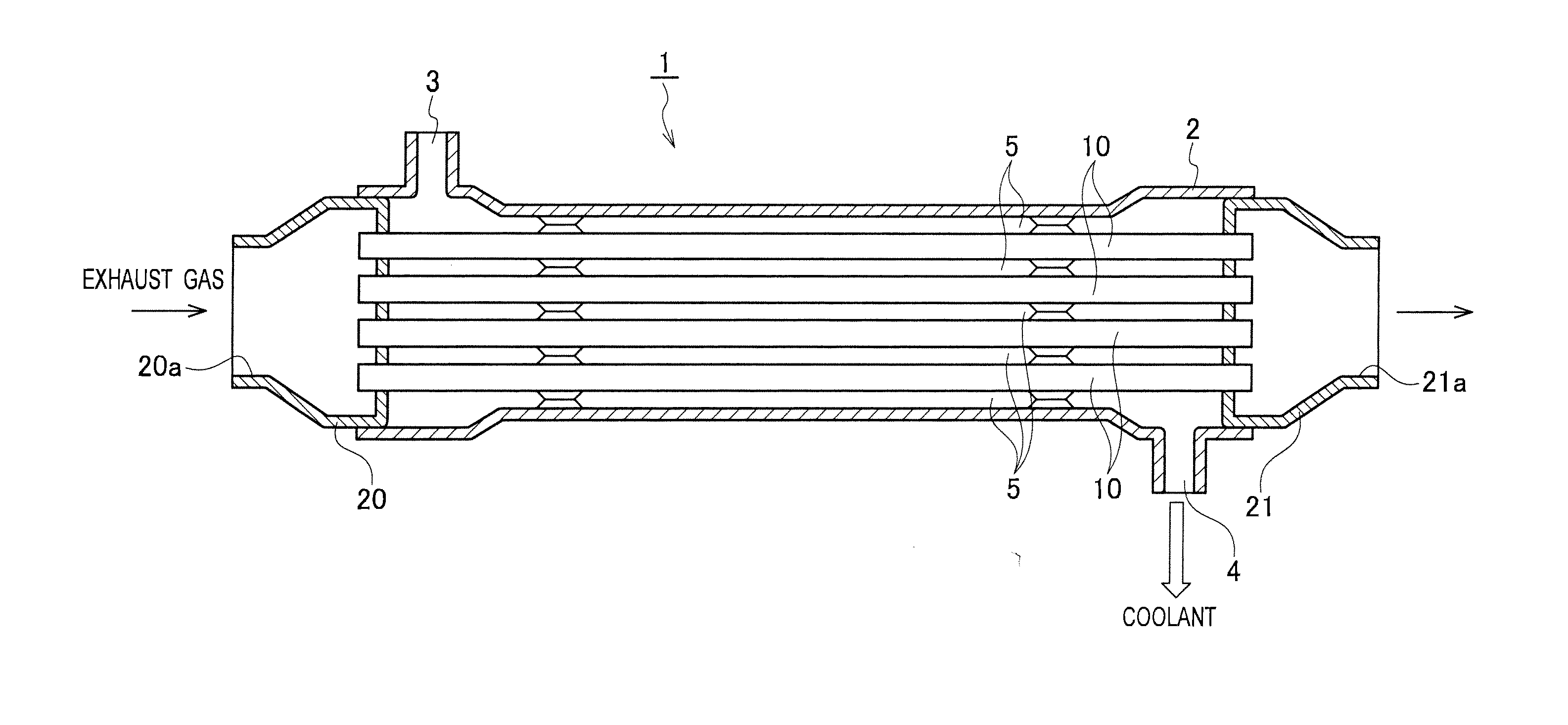
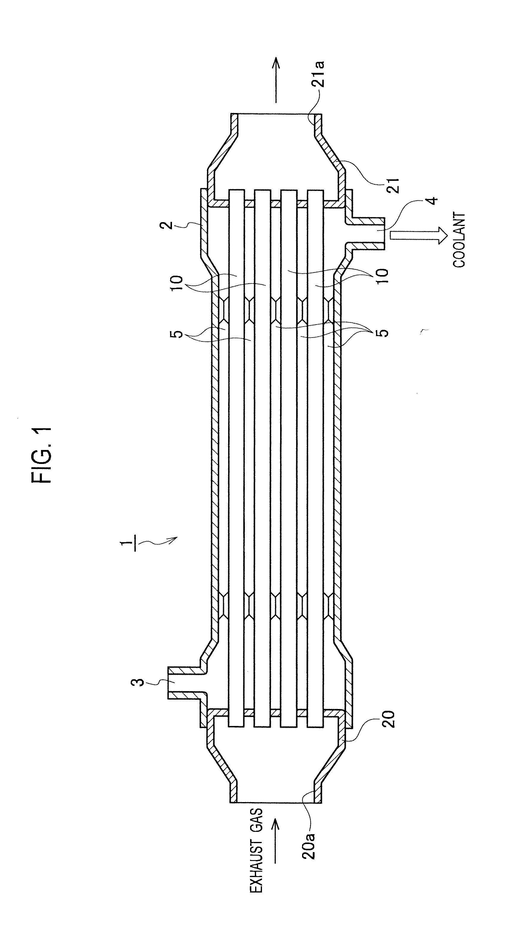
[0049]An exhaust gas heat exchanger according to a first embodiment will be explained with reference to FIG. 1 to FIG. 10. The exhaust gas heat exchanger in the present embodiment is an EGR cooler 1 for cooling recirculated exhaust gas in an EGR (exhaust gas recirculation) device for recirculating exhaust gas into intake gas in an internal combustion engine. As shown in FIG. 1, the EGR cooler 1 includes an outer case 2, plural tubes 10 accommodated in the outer case 2, and a pair of tanks 20 and 21 disposed at both ends of the plural tubes 10. These components are made of material having superior heat and corrosion resistance properties (i.e. stainless steel). These members are fixed with each other by brazing.

[0050]The outer case 2 is provided with a coolant inlet port 3 and a coolant outlet port 4 for coolant (cooling fluid). Coolant flow path 5 is formed inside the outer case 2 and outside the tubes 10. The both ends of the tubes 10 are opened to insides of the ta...

Example

Second Embodiment

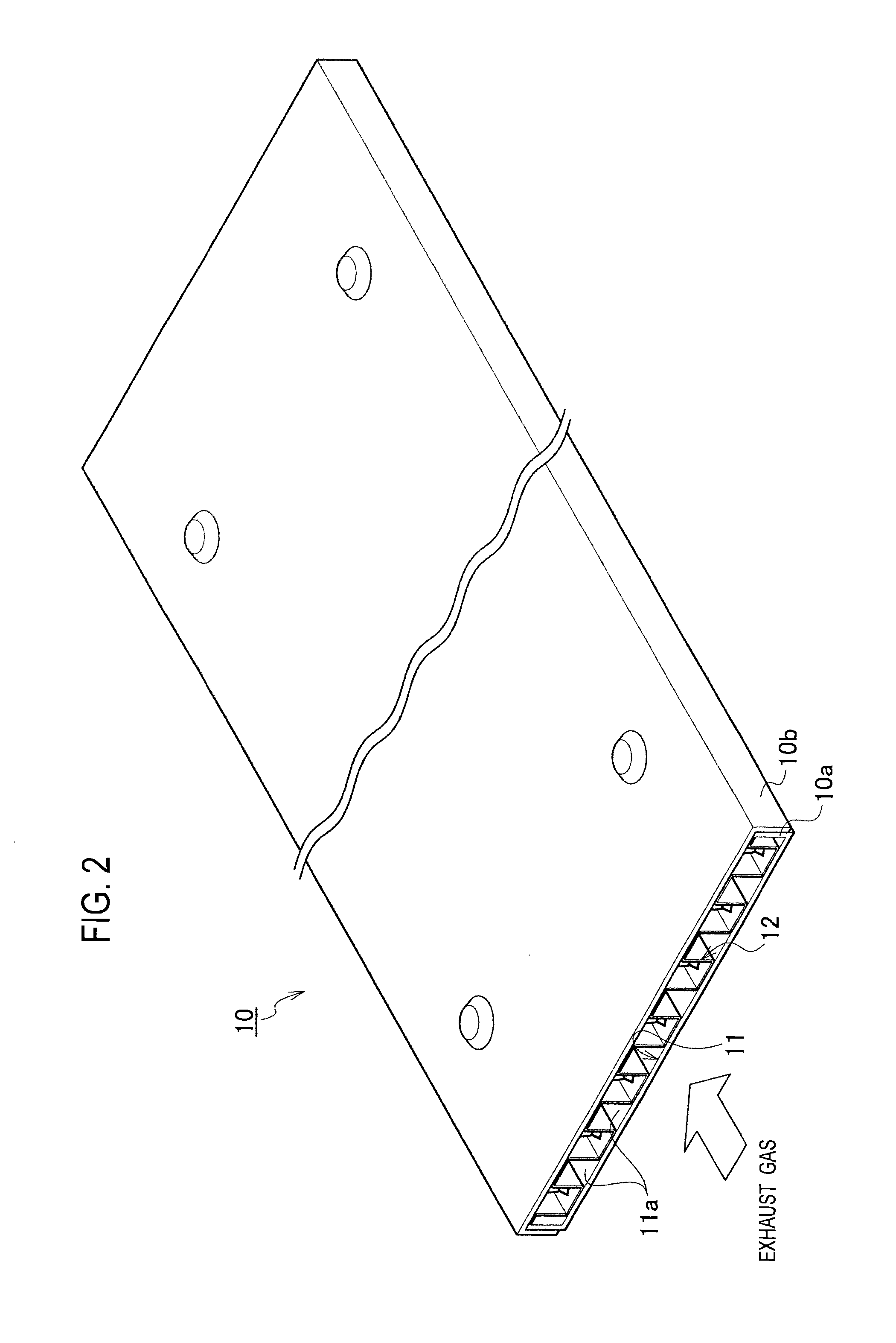
[0071]An exhaust heat exchanger according to a second embodiment will be explained with reference to FIG. 11(a). In the present embodiment, every two protruded tabs 15 are adjacent side by side along a perpendicular direction to the exhaust gas flow direction S in the segmented flow channel 11a. The adjacent two protruded tabs 15 have line-symmetrical shapes to each other with respect to the exhaust gas flow direction S. In each of the protruded tabs 15, the other lateral side 18 is located on the center of the segmented flow channel 11a. In addition, each of the protruded tabs 15 is placed obliquely so that the other lateral side 18 is located upstream from the one lateral side 17. Since other configurations are equivalent to those in the first embodiment, their redundant explanations are omitted.

[0072]According to the present embodiment, two swirl flows having different directions from each other are generated downstream of the adjacent protruded tabs 15. Therefor...

Example

Third Embodiment

[0074]An exhaust heat exchanger according to a third embodiment will be explained with reference to FIG. 11 (b). In the present embodiment, the protruded tabs 15 are aligned alternately on both sides of the center of the segmented flow channel 11a along the exhaust gas flow direction S in the segmented flow channel 11a. Each of the protruded tabs 15 on one side of the center of the segmented flow channel 11a and each of the protruded tabs 15 on another side have line-symmetrical shapes to each other with respect to the exhaust gas flow direction S. In each of the protruded tabs 15, the other lateral side 18 is located on the center of the segmented flow channel 11a. In addition, each of the protruded tabs 15 is placed obliquely so that the other lateral side 18 is located upstream from the one lateral side 17. Since other configurations are equivalent to those in the first embodiment, their redundant explanations are omitted.

[0075]According to the present embodiment,...


PUM


Abstract

An exhaust gas heat exchanger includes a tube through which exhaust gas flows, a fin disposed in the tube, and protruded tabs protruded from the tube or the fin. Each of the protruded tabs is inclined to an upstream side, and has a polygonal shape more than a quadrilateral shape having at least a bottom side, one lateral side and another lateral side. An angle of the one lateral side to the bottom side is set smaller than 90 degrees and than an angle of the other lateral side to the bottom side. The bottom side is placed to intersect with a perpendicular direction to the exhaust gas flow direction, and the other lateral side is located upstream from the one lateral side. According to the exhaust gas heat exchanger, it is possible to improve heat exchange efficiency by generating a swirl flow for facilitating heat transfer effectively.

Description

TECHNICAL FIELD[0001]The present invention relates to an exhaust gas heat exchanger for exchanging heat between exhaust gas and cooling fluid of an internal combustion engine.BACKGROUND ART[0002]A Patent Document 1 listed below discloses an exhaust gas heat exchanger for exchanging heat between exhaust gas and cooling fluid of an internal combustion engine. As shown in FIG. 20, the exhaust gas heat exchanger 100 disclosed in the Patent Document 1 includes an outer case 101, plural tubes 110 accommodated in the outer case 101, and a pair of tanks 120 and 121 disposed at both ends of the plural tubes 110.[0003]The outer case 101 is provided with a coolant inlet port 102 and a coolant outlet port 103 for coolant (cooling fluid). Coolant flow path 104 is formed inside the outer case 101 and outside the tubes 110. The both ends of the tubes 110 are opened to insides of the tanks 120 and 121, respectively. An exhaust gas inlet port 120a is formed at the tank 120 on one side, and an exhaus...

Claims


Application Information

Patent Timeline
IPC IPC(8): F01N3/02
CPCF01N3/0205F28F3/027F28D21/0003F28D7/1684F28F13/12F28F2220/00F02M26/28F02M26/32F01N1/083F01N2260/024F01N2470/12F01N1/086F01N3/043F02B29/0462F01N2240/20F01N2240/02
Inventor IWASAKI, MITSURU
Owner CALSONIC KANSEI CORP
Why Eureka
Try Eureka