System, method and apparatus for manufacturing stable cement slurry for downhole injection

Inactive Publication Date: 2014-08-28
MACH IV L L C
View PDF1 Cites 8 Cited by
  • Summary
  • Abstract
  • Description
  • Claims
  • Application Information

AI Technical Summary

Benefits of technology

[0027]Although the process of manufacturing of a foamed gas is a continuous process, the method and apparatus is designed to variably change (by manually changing the input such as time, units of volume to be processed) the various parameters of the manufacturing process such as mixing speed, mixing rate and pressure of the added air thus changing parameters in real time and without interruption to the overall manufacturing process. Due to a variable hydrostatic pressure and temperatures in a wellbore environment, there is a need to produce cement slurry of variable density to account for a changing hydrostatic pressure in a wellbore column. The system is designed to allow manufacturing of a different density of the cement slurry ranging from about 700-1400 kg/m3 (by adding different volume of the foamed gas) depending on the depth of the well and desirable compressibility dictated by the hydrostatic pressure of the well. This may be accomplished by first controlling a density of the base cement slurry, ranging from about 1400-1900 kg/m3, including controlling (and testing) the amount of water and chemical additives that dictate density, viscosity, set time and compressive strength of the base cement slurry as it is almost impossible to change the base slurry density over the c

Problems solved by technology

This is important in oil well applications since the formation of bleed channels and voids can

Method used


Image

  • System, method and apparatus for manufacturing stable cement slurry for downhole injection
  • System, method and apparatus for manufacturing stable cement slurry for downhole injection
  • System, method and apparatus for manufacturing stable cement slurry for downhole injection

Examples


Embodiment Construction

[0040]Referring now to the drawings, wherein like reference numbers are used herein to designate like elements throughout, the various views and embodiments of a system, method and apparatus for producing stable, lightweight cement slurry for downhole injection are illustrated and described, and other possible embodiments are described. The figures are not necessarily drawn to scale, and in some instances the drawings have been exaggerated and / or simplified in places for illustrative purposes only. One of ordinary skill in the art will appreciate the many possible applications and variations based on the following examples of possible embodiments.

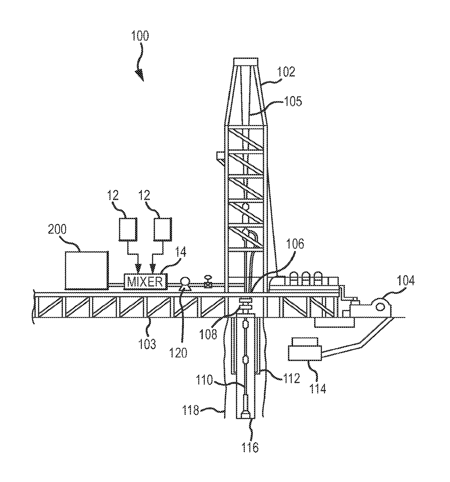
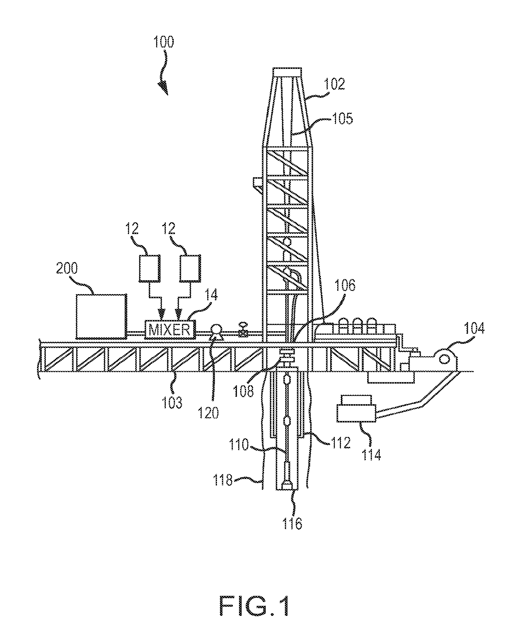
[0041]Referring now to FIG. 1, there is depicted a typical drilling apparatus 100 used in oilfield production. The apparatus normally includes a derrick 102 extending above a drilling platform 103. The derrick provides a means of rising and lowering drill casing and a drill pipe as the wellbore is formed. As illustrated, apparatus 100 inclu...


PUM

PropertyMeasurementUnit
Weightaaaaaaaaaa
Fractionaaaaaaaaaa
Pressureaaaaaaaaaa

Abstract

A method for manufacturing stable lightweight cement slurry in a continuous manner for downhole injection comprising the steps of manufacturing a foamed gas having desired density ranging from about 2.15 to about 2.35 lb/cubic ft. and utilizing foam stabilizing nonionic surfactant. And, an apparatus for carrying out the method.

Description

CROSS-REFERENCE TO RELATED APPLICATIONS[0001]This U.S. Utility Application is a continuation application, claiming priority pursuant to 35 U.S.C. §365(c) to the Patent Cooperation Treaty Application, Ser. No. PCT / US2013 / 21780 titled, “SYSTEM, METHOD AND APPARATUS FOR MANUFACTURING STABLE CEMENT SLURRY FOR DOWNHOLE INJECTION,” the specification of which is incorporated herein by reference for all purposes, and which claims priority to the U.S. Provisional Application Ser. No. 61 / 514,638, titled “COMPOSITION AND METHOD FOR ENTRAINING AIR IN CEMENT SLURRY FOR DOWNHOLE INJECTION,” filed Jan. 17, 2012, the specification of which is incorporated herein by reference for all purposes.[0002]This application is also related to U.S. patent application Ser. No. 12 / 748,883, filed on Mar. 29, 2010, entitled “SYSTEM, METHOD AND APPARATUS FOR ENTRAINING AIR IN CONCRETE,” published on Sep. 30, 2010 under publication No. US 2010 / 0246312, the specification of which is incorporated herein by reference ...

Claims


Application Information

Patent Timeline
IPC IPC(8): C04B38/10E21B33/14
CPCC04B38/103E21B33/14E21B33/138E21B21/14C04B28/02C09K8/473C04B2103/406C04B24/2682C04B38/10
Inventor WELKER, CHARLES D.
Owner MACH IV L L C
Why Eureka
Try Eureka