Pump probe measuring device

a technology of measuring device and probe, which is applied in the direction of scanning probe microscopy, scanning probe techniques, instruments, etc., can solve the problems of mechanical vibration, major limitations in the frequency of modulation, and the amplitude of modulation of 10 has major limitations, so as to achieve high sensitiveness, accurate and stable measurement

Inactive Publication Date: 2014-08-28
JAPAN SCI & TECH CORP
View PDF4 Cites 9 Cited by
  • Summary
  • Abstract
  • Description
  • Claims
  • Application Information

AI Technical Summary

Benefits of technology

[0029]According to the present invention, in a time-resolved measurement using a pulse laser covering a femtosecond region, faint signals can be measured highly sensitively, accurately, and stably in a wide measurement range including phenomena having short to long relaxation time, without modulating the intensity of ill

Problems solved by technology

However, the device as shown in FIG. 10 has major limitations in the amplitude of modulation and in the frequency of modulation.
In using an amplitude about 1.5 cm or more, or a frequency about 10 Hz, problems may arise.
The mechanical vibration may be generated and give bad influences to the optical device located around.
It becomes impossible to realize the accurate modulation due to the deformation of the driving mechanism itse

Method used


Image

  • Pump probe measuring device
  • Pump probe measuring device
  • Pump probe measuring device

Examples


first embodiment

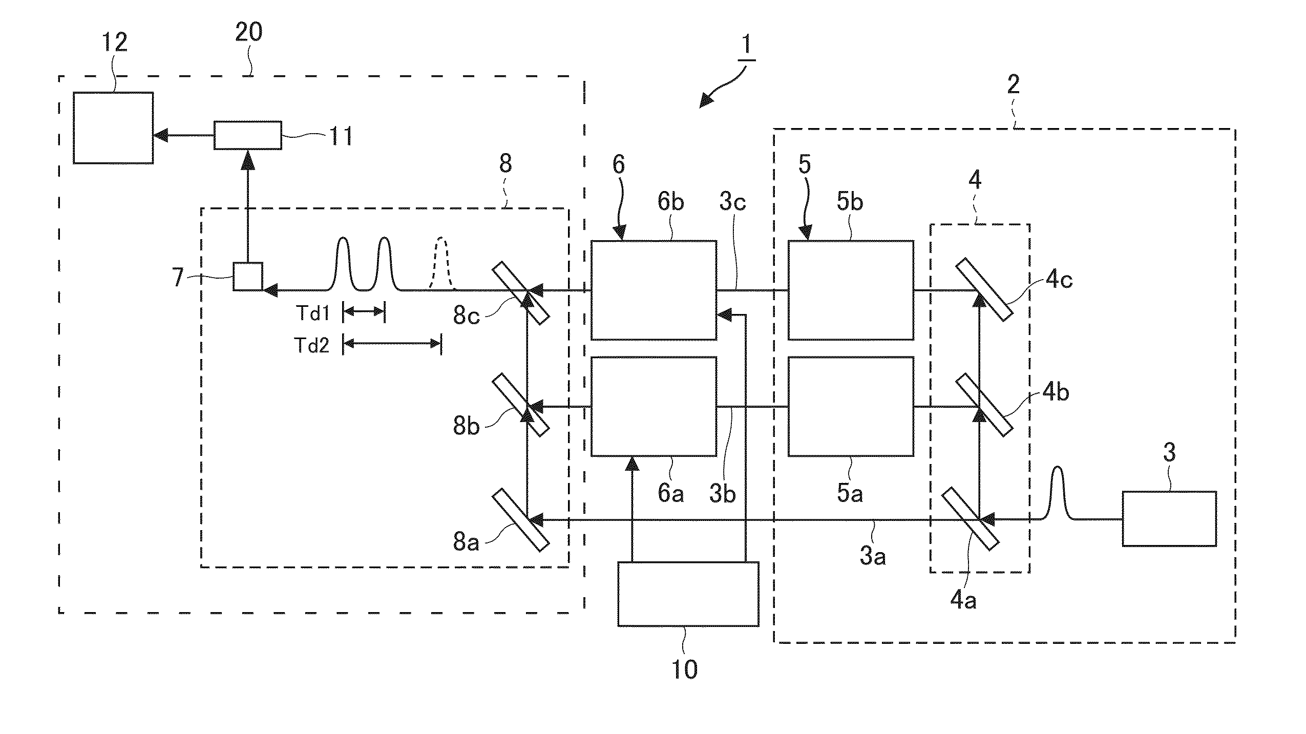
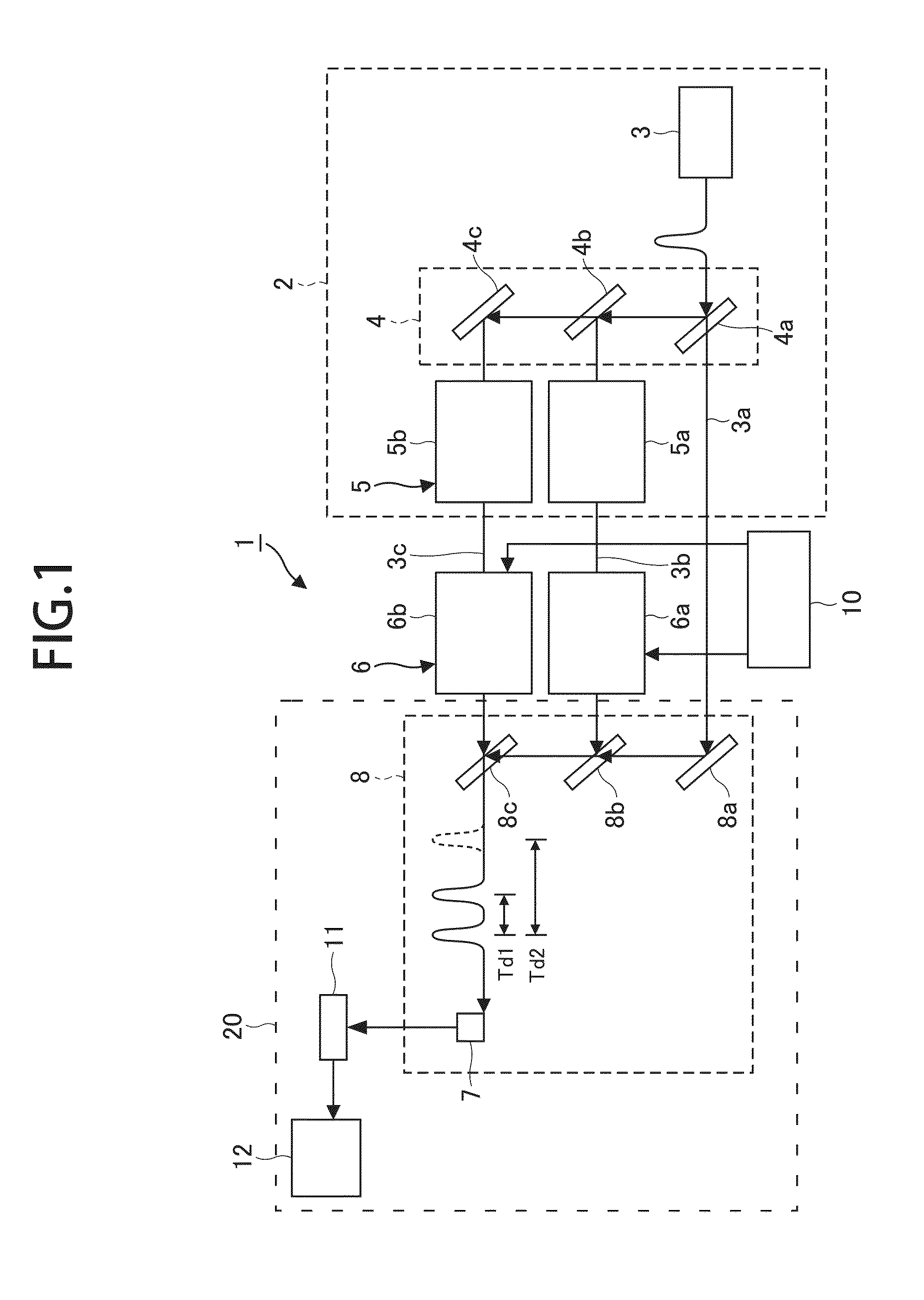
[0069]FIG. 1 is a view illustrating a typical configuration of a pump probe measuring device 1 according to the first embodiment of the present invention. As shown in FIG. 1, the pump probe measuring device 1 includes: an ultrashort optical pulse laser generator 2 for generating a first ultrashort optical pulse train which is a pump light 3a, a second ultrashort optical pulse train, which is a first probe light 3b, and a third ultrashort optical pulse train which is a second probe light 3c; an optical shutter unit 6 to which the second and the third ultrashort optical pulse trains are introduced; an optical shutter control unit 10 for controlling the optical shutter unit 6; an irradiation optical system 8 for directing the pump light 3a and the probe lights 3b, 3c to a sample; and a detecting unit 20 including a sensor 11 for detecting a probe signal from the sample 7 and a phase-sensitive detecting means 12 for detecting the probe signal.

[0070]The ultrashort optical pulse laser gen...

second embodiment

[0108]FIG. 6 is a schematic view illustrating the configuration of a pump probe measuring device 30 according to a second embodiment of the present invention. As shown in FIG. 6, the pump probe measuring device 30 according to the second embodiment of the present invention differs from the pump probe measuring device 1 according to the first embodiment in that an optical shutter unit 6A is provided instead of the optical shutter unit 6 as shown in FIG. 1. The optical shutter unit 6A includes: a Pockels cell, which functions as an optical shutter 6c; a fifth half mirror 6e; a polarization rotation element 31; and a third mirror 6d. The irradiation optical system 8A includes the second mirror 8a and the third half mirror 8b. In other words, the number of half mirrors used in the irradiation optical system 8A in this embodiment is one less than that of the irradiation optical system 8 as shown in FIG. 1. The optical shutter control unit 10 has a circuit for generating 1 kHz rectangular...

third embodiment

[0118]FIG. 7 is a schematic view illustrating the configuration of a pump probe measuring device 40 according to a third embodiment of the present invention. As shown in FIG. 7, the pump probe measuring device 40 according to the third embodiment differs from the pump probe measuring device 1 according to the first embodiment in that an ultrashort optical pulse laser generator 2A is provided, instead of the above-mentioned ultrashort optical pulse laser generator 2. The ultrashort optical pulse laser generator 2A includes three laser light sources 43, namely a first laser light source 43a for generating a pump light 3a, a second laser light source 43b for generating a first probe light 3b, and a third laser light source 43c for generating a second probe light 3c.

[0119]First, the optical path of the pump light 3a from the first laser light source 43a to the sample 7 will be described. The light from the first laser light source 43a is reflected by the mirror 8a, penetrates the third...


PUM


Abstract

A pump probe measuring device (1) comprises: an ultrashort optical pulse laser generator (2) for generating a first ultrashort optical pulse train which is a pump light (3a), second and third ultrashort optical pulse trains (3b), (3c) which are probe lights; an optical shutter unit (6) to which the second and the third ultrashort pulse trains (3b), (3c) are introduced; and a detecting unit (20) including an irradiation optical system (8) for directing the pump light (3a), the first probe light (3b) and the second probe light (3c) to a sample (7), a sensor (11) for detecting a probe signal from the sample (7), and a phase-sensitive detecting means (12) connected to the sensor (11). An optical shutter control unit (10) periodically modulates the delay time of the first probe light (3b) and that of the second probe light (3c) with respect to the pump light (3a), and the modulated first and second probe lights (3a), (3b) illuminate the sample (7) alternately to detect the probe signals from the sample (7) by the phase-sensitive detecting means (12) in synchronization with the periodic modulation signal of the delay time.

Description

TECHNICAL FIELD[0001]The present invention relates to a pump probe measuring device.BACKGROUND ART[0002]To measure ultrafast phenomena that occur in picosecond (ps) to femtosecond (fs) regions, measurements using an ultrashort pulse laser are carried out widely. For example, in a pump probe reflectance measurement, a high-intensity pump pulse is focused to an object to be measured first to excite the sample instantaneously. Then, while the excited state is being relaxed, an irradiation of a low-intensity probe pulse is applied, and the intensity of the reflected light is measured. The measured intensity of the reflected light is proportional to the reflectance of the sample at the moment when it is hit by the probe pulse. By measuring the intensity of the reflected light while gradually changing the delay time of the probe pulse with respect to the pump pulse, change in the reflectance of the sample between before and after the excitation can be observed with the time resolution com...

Claims


Application Information

Patent Timeline
IPC IPC(8): G01N21/55
CPCG01N21/55G01N2021/1791B82Y35/00G01N21/1717G01N21/636G01N2021/1719G01N2021/1725G01N2021/1789G01N2201/0697G01Q60/12H01J37/244H01J37/26H01J2237/24507H01J2237/24564H01J2237/2818
Inventor SHIGEKAWA, HIDEMITAKEUCHI, OSAMU
Owner JAPAN SCI & TECH CORP
Why Eureka
Try Eureka