Wavelength variable interference filter, optical filter device, optical module, and electronic apparatus

a technology of wavelength variable interference and filter, which is applied in the direction of optics, optical elements, instruments, etc., can solve problems such as disconnection, and achieve the effects of improving the reliability of electronic devices, high precision, and improving the connection reliability of wiring

Inactive Publication Date: 2014-08-28
SEIKO EPSON CORP
View PDF3 Cites 11 Cited by
  • Summary
  • Abstract
  • Description
  • Claims
  • Application Information

AI Technical Summary

Benefits of technology

[0053]From this, it is possible to reliably provide electrical conduction between the first reflective film and the first connection electrode and electrical conduction between the second reflective film and the second connection electrode, to improve connection reliability of wiring, and to improve reliability of the electronic apparatus. Therefore, the electronic apparatus can carry out processing with high precision on the basis of light extracted by the wavelength variable interference filter.

Problems solved by technology

However, when a thick connection electrode and a thin reflective film are formed in an overlapping manner, metal atoms of the thin reflective film are diffused toward the connection electrode due to external factors, such as heat, or change over time, and there is concern about disconnection.

Method used


Image

  • Wavelength variable interference filter, optical filter device, optical module, and electronic apparatus
  • Wavelength variable interference filter, optical filter device, optical module, and electronic apparatus
  • Wavelength variable interference filter, optical filter device, optical module, and electronic apparatus

Examples


first embodiment

Configuration of Spectroscopic Measurement Apparatus

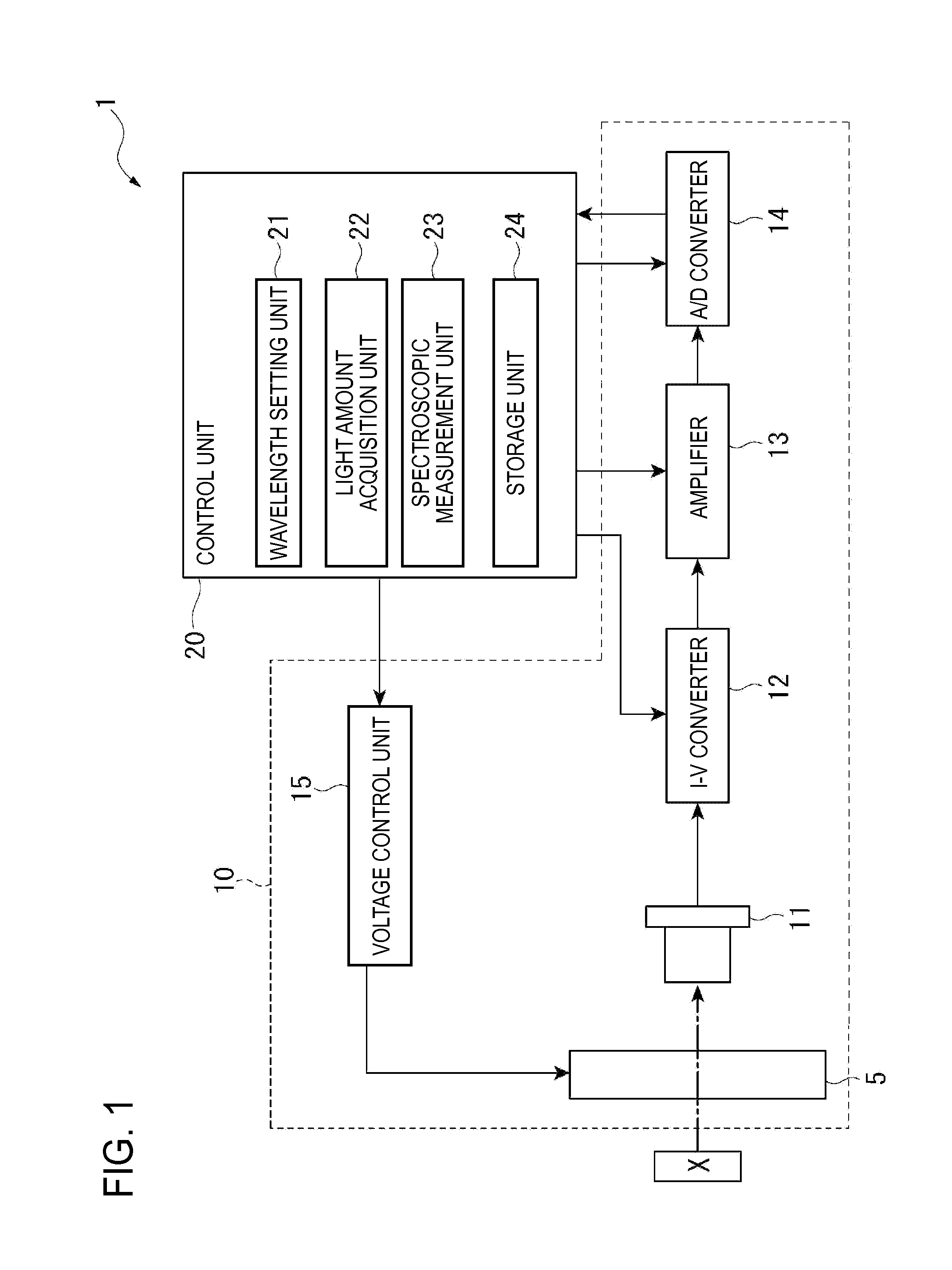
[0073]FIG. 1 is a schematic view showing a configuration of a spectroscopic measurement apparatus according to a first embodiment of the invention.

[0074]A spectroscopic measurement apparatus 1 is an electronic apparatus according to the invention, and is an apparatus which measures the spectrum of light to be measured on the basis of light to be measured reflected by an object X to be measured. In this embodiment, although an example where light to be measured reflected by the object X to be measured is measured will be described, when a luminous body, such as a liquid crystal panel, is used as an object X to be measured, for example, light emitted from the luminous body may be used as the light to be measured.

[0075]As shown in FIG. 1, the spectroscopic measurement apparatus 1 includes an optical module 10 and a control unit 20.

Configuration of Optical Module

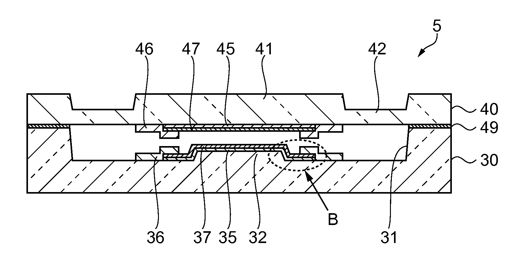
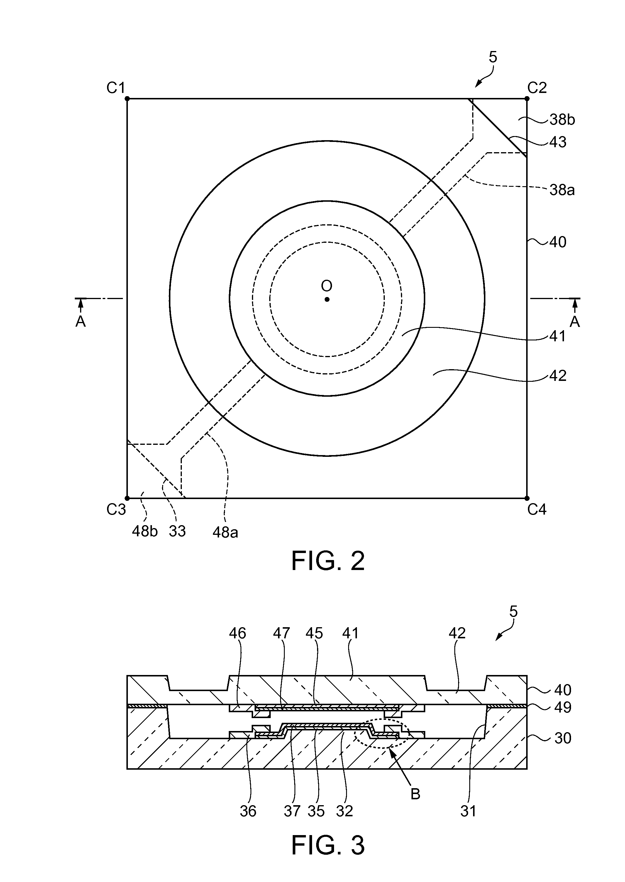
[0076]The optical module 10 includes a wavelength variable interference fi...

second embodiment

[0204]Next, a second embodiment of the invention will be described referring to the drawings.

[0205]In the spectroscopic measurement apparatus 1 of the first embodiment, the wavelength variable interference filter 5 is provided directly in the optical module 10. However, an optical module has a complicated configuration, and in particular, it is difficult to provide the wavelength variable interference filter 5 directly in a small optical module. In this embodiment, an optical filter device in which the wavelength variable interference filter 5 can be easily provided in an optical module will be described below.

[0206]FIG. 12 is a sectional view showing the schematic configuration of an optical filter device according to the second embodiment of the invention.

[0207]As shown in FIG. 12, an optical filter device 60 includes a wavelength variable interference filter 5, and a housing 61 which stores the wavelength variable interference filter 5.

[0208]The housing 61 includes a base substra...

third embodiment

[0218]Next, an electronic apparatus which uses the wavelength variable interference filter described in the first embodiment will be described. In a third embodiment, for example, a colorimetric apparatus which measures chromaticity of an object to be measured will be described.

[0219]FIG. 13 is a schematic view showing a configuration of a colorimetric apparatus.

[0220]A colorimetric apparatus 80 includes a light source device 82 which irradiates light on a test object A, a colorimetric sensor 84 (optical module), a control device 86 which controls the overall operation of the colorimetric apparatus 80.

[0221]The colorimetric apparatus 80 is an apparatus which irradiates light onto the test object A from the light source device 82, receives light to be tested reflected by the test object A by the colorimetric sensor 84, and analyzes and measures chromaticity of light to be tested on the basis of a detection signal output from the colorimetric sensor 84.

[0222]The light source device 82...


PUM


Abstract

The thickness of a first drive electrode is greater than the sum of the thickness of a first reflective film and the thickness of a first conductive film, the first drive electrode extends from the surface of a fixed substrate to the surface of the outer edge portion of the first conductive film and is in contact with the first conductive film, the thickness of a second drive electrode is greater than the sum of the thickness of a second reflective film and the thickness of a second conductive film, and the second drive electrode extends from the surface of a movable substrate to the surface of the outer edge portion of the second conductive film and is in contact with the second conductive film.

Description

BACKGROUND[0001]1. Technical Field[0002]The present invention relates to a wavelength variable interference filter, an optical filter device, an optical module, and an electronic apparatus.[0003]2. Related Art[0004]An apparatus which uses a wavelength variable interference filter and measures the spectrum of incoming light is known.[0005]A variable interference device described in JP-A-1-94312 has a configuration in which a reflective film functions as a driving electrode and a configuration in which a reflective film functions as an electrostatic capacitance monitoring electrode.[0006]In the structure of JP-A-1-94312, in order for the reflective film to function as the driving electrode or the electrostatic capacitance monitoring electrode, it is necessary to wire a connection electrode which is connected to the reflective film.[0007]In order for the reflective film to have a light transmission characteristic and a light reflection characteristic, the reflective film is formed to h...

Claims


Application Information

Patent Timeline
Patent Type & Authority Applications(United States)
IPC IPC(8): G02B26/00
CPCG02B26/001G02B5/28G02B5/284G02B5/285G02B27/00
Inventor SHINTO, SUSUMUSAKASHITA, TOMOKI
Owner SEIKO EPSON CORP
Why Eureka
Try Eureka