Inversion Delivery Device and Method For A Prosthesis

a technology of inversion delivery and prosthesis, which is applied in the field of inversion delivery device and method for prosthesis, can solve the problems of stenosis, narrowing of the passageway through the valve, heart failure and ultimately death, and great discomfort, and achieves precise positioning and inversion, limiting the advancement of a portion, and precise positioning

Active Publication Date: 2014-08-28
EDWARDS LIFESCIENCES CORP
View PDF1 Cites 23 Cited by
  • Summary
  • Abstract
  • Description
  • Claims
  • Application Information

AI Technical Summary

Benefits of technology

[0020]Through attachment to the aortic flare, the delivery device of the present invention enables precise positioning and inversion by limiting advancement of a portion of the implant while continuing to advance the remainder of the device. Hence, inversion is effected at a location selected by the user, independent of patient anatomy or geometric interference. One embodiment of the invention achieves this precise positioning through attachment to a distal end of the device.
[0021]Two aspects of the present invention provide reliable performance of the delivery device of the present invention. A first aspect is an attachment mechanism that can be mounted to a braided device without requiring significant modification to the function of the braided device. This attachment mechanism provides device stabilization during the support structure inversion process. This attachment mechanism provides both attachment to the device and a release capability in some embodiments. A second aspect of the present invention includes positioning mechanisms that prevent movement of the device in the target location during the inversion process.
[0022]Another aspect of the present invention provides freedom of motion to the support structure anchors as the device is being deployed, but automatically actuates anchor locking mechanisms when the device has been advanced to the appropriate position for the inversion process. This automatic actuation reduces the need for physician involvement or judgment in the tensioning and setting of the anchor mechanisms. The nature of the mechanism also accounts for manufacturing and use tolerances, precisely tuning the anchor locking mechanism to the selected valve and delivery system.

Problems solved by technology

Such immobility also may lead to a narrowing, or stenosis, of the passageway through the valve.
The increased resistance to blood flow that a stenosed valve presents can eventually lead to heart failure and ultimately death.
Naturally, this is a heavily invasive procedure and inflicts great trauma on the body leading usually to great discomfort and considerable recovery time.
One particular drawback with the percutaneous approach disclosed in the Andersen '614 patent is the difficulty in preventing leakage around the perimeter of the new valve after implantation.
Since the tissue of the native valve remains within the lumen, there is a strong likelihood that the commissural junctions and fusion points of the valve tissue (as pushed apart and fixed by the stent) will make sealing around the prosthetic valve difficult.
In practice, this has often led to severe leakage of blood around the stent apparatus.
Other drawbacks of the Andersen '614 approach pertain to its reliance on stents as support scaffolding for the prosthetic valve.
First, stents can create emboli when they expand.
Second, stents are typically not effective at trapping the emboli they dislodge, either during or after deployment.
Third, stents do not typically conform to the features of the native lumen in which they are placed, making a prosthetic valve housed within a stent subject to paravalvular leakage.
Fourth, stents are subject to a tradeoff between strength and compressibility.
Fifth, stents cannot be retrieved once deployed.
Sixth, stents have an inherent strength that is not adjustable.
The force is usually strong enough to crack or deform thrombosis, thereby causing pieces of atherosclerotic plaque to dislodge and become emboli.
An additional concern related to displacing an aortic valve is the risk of conduction disturbances (i.e. left bundle branch block) due to the close proximity of the conduction pathways to the native valve structure.
Excessive radial force applied at the native valve site increases the risk of irritation or damage to the conduction pathway and heart block.
As to the second drawback, if emboli are created, expanded stents usually have members that are too spaced apart to be effective to trap any dislodged material.
The third drawback is due to the relative inflexibility of stents.
Due to the non-conforming nature of stents, this seal is hard to achieve, especially when displacing stenosed valve leaflets.
The fourth drawback is the tradeoff between compressibility and strength.
Most stents suitable for use in a valve are not compressible enough to be placed in a thin catheter, such as a 18Fr catheter.
Larger delivery catheters are more difficult to maneuver to a target area and also result in more trauma to the patient.
The fifth drawback of stents is that they are not easily retrievable.
Thus, if a physician is unsatisfied with the deployed location or orientation of a stent, there is little he or she can do to correct the problem.
The sixth drawback listed above is that stents have an inherent strength and are thus not adjustable.
Once a stent is selected and deployed, there is little a physician can do if the stent proves to be too strong or too weak.
It has been found, however, that in some cases, depending on target location and patient anatomy, there is insufficient space in a distal axial direction beyond the target location to efficiently use this delivery device.
For example, some patients may have limited left ventricular space, which may prohibit the use of the backstop device.

Method used


Image

  • Inversion Delivery Device and Method For A Prosthesis
  • Inversion Delivery Device and Method For A Prosthesis
  • Inversion Delivery Device and Method For A Prosthesis

Examples


Embodiment Construction

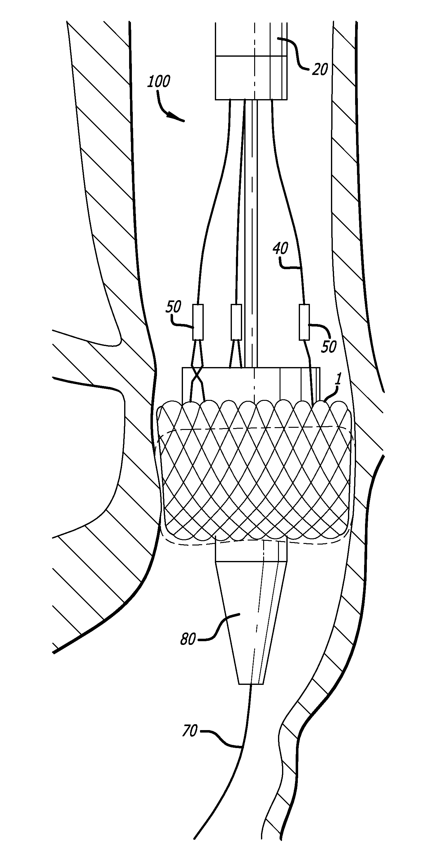
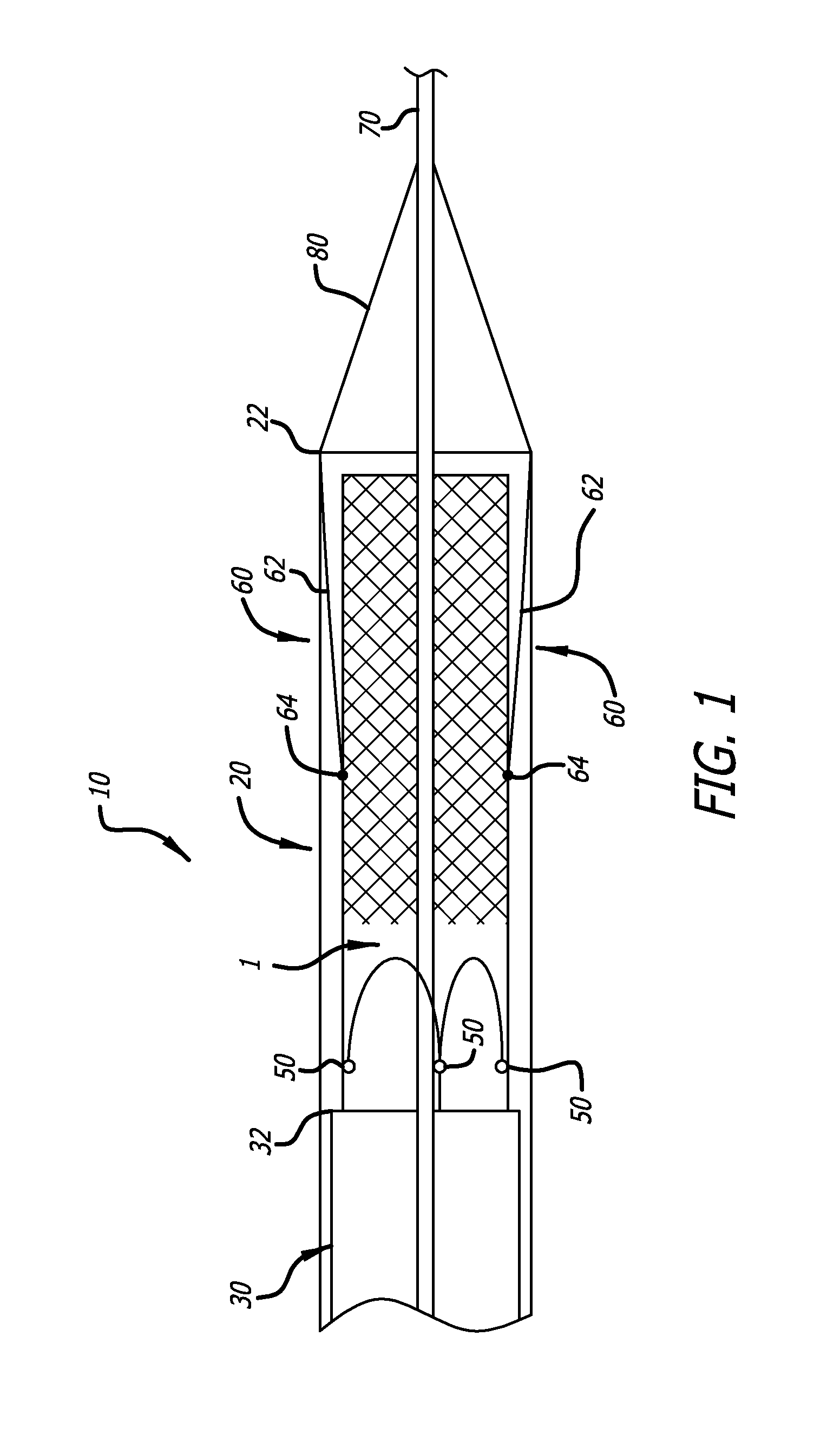
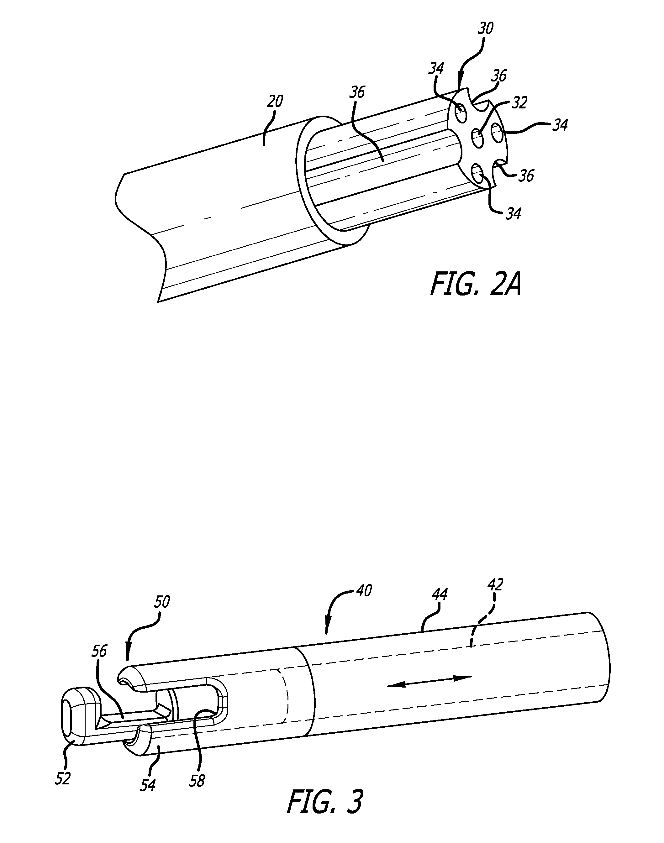
[0052]Referring now to the Figures and first to FIG. 1, there is shown a distal end of a delivery device 10 of the present invention. The delivery device generally includes a delivery catheter 20, and a pusher catheter 30 slidably contained within the delivery catheter 20. The pusher catheter 30 is preferably a multi-lumen catheter containing lumens for slidably containing and maintaining alignment of three attachment cables 40 (hereinafter “valve retention cables”) (see FIG. 3), each of which has a releasable grasping mechanism 50 at a distal end thereof. The delivery device 10 also includes at least one positioning mechanism 60 used to aid the tool or implant 1 in achieving a folded, deployed configuration from an extended, unfolded, navigation configuration. In one embodiment, the at least one positioning mechanism 60 is attached to a distal end of the delivery catheter 20. In another embodiment, the at least one positioning mechanism 60 is slidably contained within the delivery ...


PUM


Abstract

A delivery device usable to deliver an inverting implant is provided that includes a positioning mechanism that automatically initiates the inversion process once a predetermined length of the implant has exited a delivery catheter. The positioning mechanism allows the implant to be safely and accurately deployed with reduced operator experience and in a greater variety of target locations.

Description

RELATED APPLICATIONS[0001]This application is a continuation of U.S. patent application Ser. No. 13 / 657,800 filed Oct. 22, 2012, entitled Inversion Delivery Device And Method For A Prosthesis, which is a Continuation-In-Part of U.S. patent application Ser. No. 13 / 473,475, filed on May 16, 2012, entitled Inversion Delivery Device and Method for a Prosthesis, which claims priority to U.S. Provisional Application Ser. No. 61 / 486,682 filed May 16, 2011 entitled Inversion Delivery Device and Method For A Prosthesis, which is hereby incorporated herein by reference in its entirety.BACKGROUND OF THE INVENTION[0002]There has been a significant movement toward developing and performing cardiovascular surgeries using a percutaneous approach. Through the use of one or more catheters that are introduced through, for example, the femoral artery, tools and devices can be delivered to a desired area in the cardiovascular system to perform many number of complicated procedures that normally otherwi...

Claims


Application Information

Patent Timeline
Patent Type & Authority Applications(United States)
IPC IPC(8): A61F2/24
CPCA61F2/2439A61F2002/9534A61F2002/9517A61F2/9517A61F2/2427A61F2/2436A61F2/2418
Inventor WILSON, ROBERT FOSTERSVENDSEN, CASSANDRANELSON, DALE K.GAINOR, JOHN P.
Owner EDWARDS LIFESCIENCES CORP
Why Eureka
Try Eureka