
Ultra-low fractional area coverage flow diverter for treating aneurysms and vascular diseases

a flow diverter and fractional area coverage technology, applied in blood vessels, prostheses, paper/cardboard articles, etc., can solve the problems of insufficient flow diversion of conventional stent structures, inability to precisely control the porosity to a tolerance of 1 micron, and inability to generate specific shapes and distributions precisely. , to achieve the effect of low profile and without intimal hyperplasia

Inactive Publication Date: 2014-09-04
RGT UNIV OF CALIFORNIA
View PDF6 Cites 25 Cited by
  • Summary
  • Abstract
  • Description
  • Claims
  • Application Information

AI Technical Summary

Benefits of technology

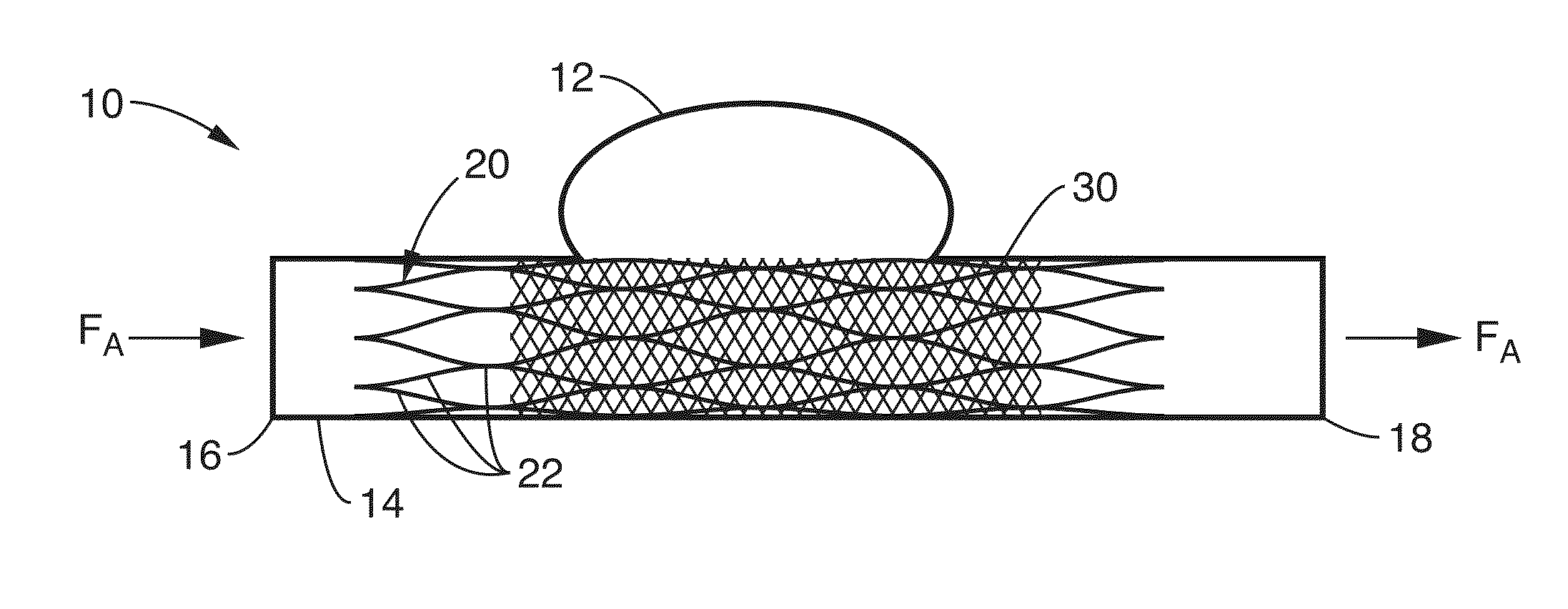
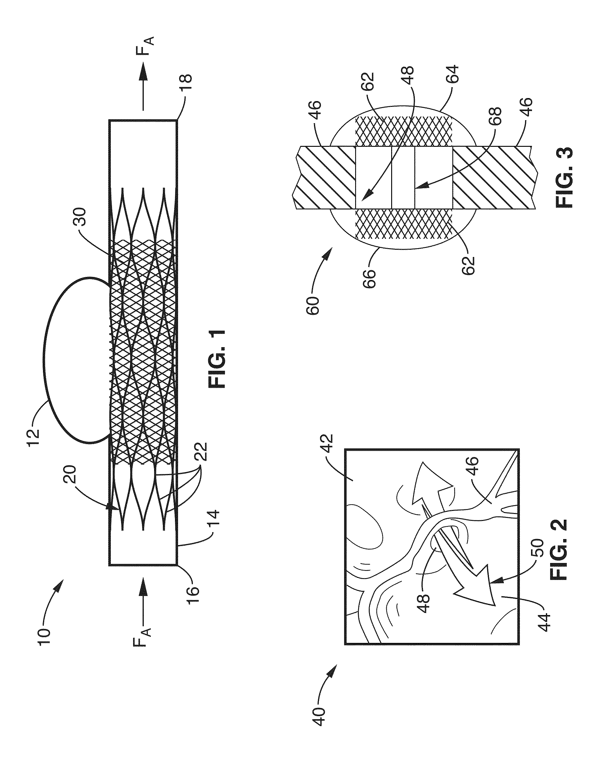
The present invention is about creating thin films that can be used to make vascular flow diversion devices. These devices are designed to treat vascular diseases like aneurysms. The thin films are made using micro-machining techniques, which allow for the creation of highly flexible and elastic structures. These devices do not cause blood clotting or narrowing of the blood vessels, and have been shown to reduce the velocity and vorticity of blood flow in a simulated aneurysm. The invention has several benefits, including the creation of low-profile devices that can be easily delivered without folding.

Problems solved by technology

Conventional stent structures do not provide sufficient flow diversion to treat aneurysms.
PTFE, Dacron and other polymer structures are fabricated in such a fashion that it is extremely difficult to precisely control the porosity to a tolerance of 1 micron.
Even in cases where porosity can macroscopically be controlled in these materials, specific shapes and distributions cannot be generated precisely.
For example, it is highly difficult, if not impossible, to specifically fabricate a circular or diamond shape pattern that is regular and repeating into structures comprising these materials.
This increases the size of any flow diversion device without providing significant benefit in regards to the thickness direction.
However, this procedure requires a craniotomy (an opening in the skull) and is not always applicable depending on the aneurysm size, location, and complexity.
While coils are beneficial, they can only be used for aneurysms with “necks” narrow enough to hold coils in the aneurysm.
This procedure is complicated (it involves two types of devices: a stent and multiple coils), sometimes does not produce aneurysm occlusion, and is limited by the physical size of the stent's delivery system.
While they can wall off aneurysms by circumferentially covering the wall of an artery, they have been far too bulky for use as neurovascular stents or in other flow diversion vascular systems requiring a low profile.

Method used


Image

  • Ultra-low fractional area coverage flow diverter for treating aneurysms and vascular diseases
  • Ultra-low fractional area coverage flow diverter for treating aneurysms and vascular diseases
  • Ultra-low fractional area coverage flow diverter for treating aneurysms and vascular diseases

Examples


embodiment 1

[0123]2. A flow diversion apparatus according to wherein the treatment region comprises an aneurism; and wherein the clotting cascade is configured to occlude the aneurism.

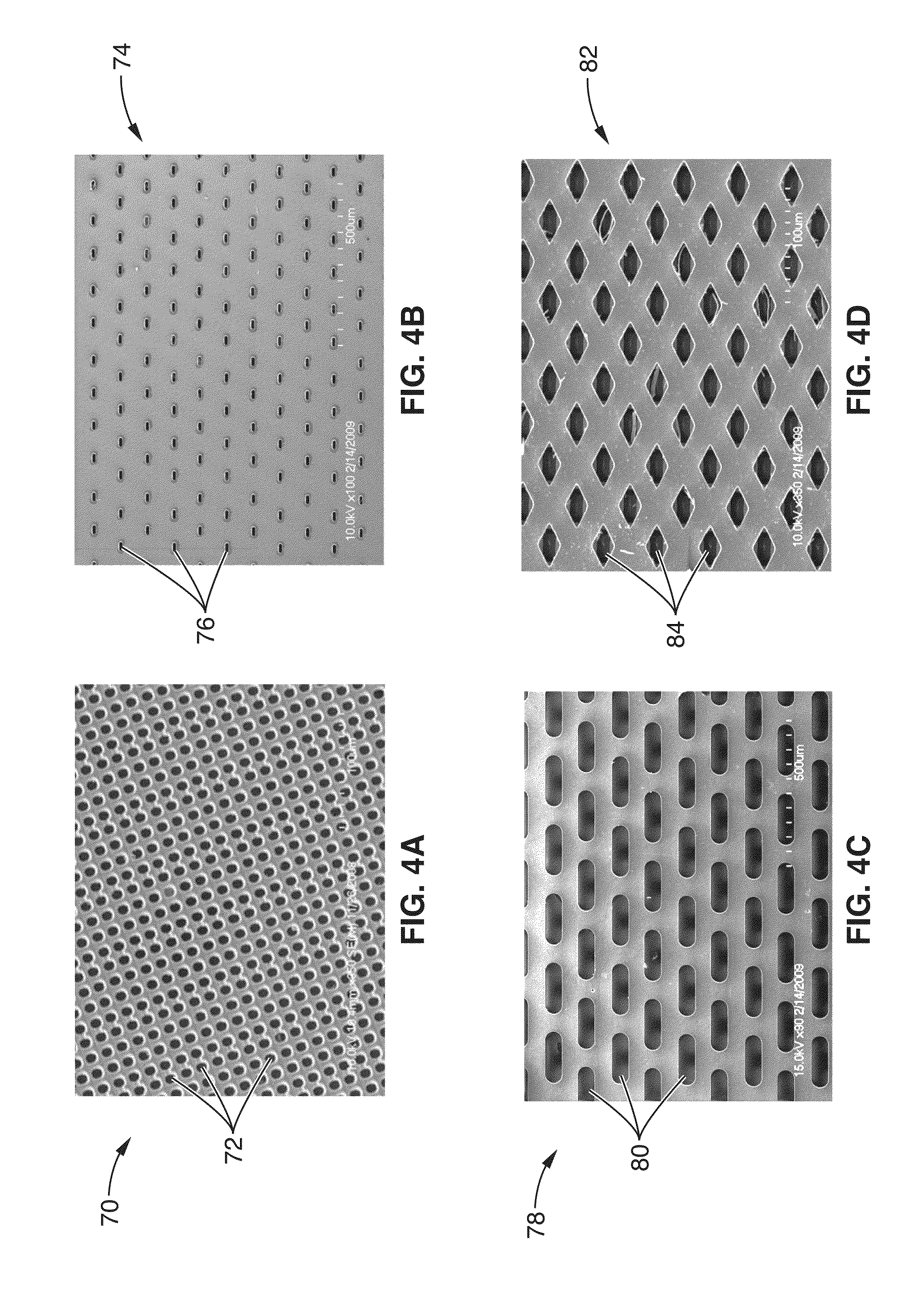
[0124]3. The flow diversion apparatus of embodiment 1, wherein the fenestrations have a pore size of less than approximately 500 microns.

embodiment 3

[0125]4. The flow diversion apparatus of embodiment 3, wherein the fenestrations have a pore size of less than approximately 300 microns.

[0126]5. The flow diversion apparatus of embodiment 3, wherein the fenestrations have a pore size between approximately 200 microns and 400 microns.

[0127]6. The flow diversion apparatus of embodiment 1, wherein the thin-film sheet comprises a surface coverage of less than approximately 30%.

embodiment 6

[0128]7. The flow diversion apparatus of embodiment 6, wherein the thin-film sheet comprises a surface coverage of between approximately 5% and 20%.

[0129]8. The flow diversion apparatus of embodiment 1, wherein the thin-film sheet comprises thin-film Nitinol having at least one super-hydrophilic surface.


PUM

PropertyMeasurementUnit
pore sizeaaaaaaaaaa
pore sizeaaaaaaaaaa
pore sizeaaaaaaaaaa

Abstract

A flow diverter is described and fabricated using ultra-thin porous thin-film Nitinol, and is configured for implantation to a treatment site within a vessel for significant reduction in an intra-aneurismal flow velocity and vorticity. Using small size pores in a coverage area of only 10%, a 90% reduction in flow velocity into a pseudo-aneurysm can be achieved, with an almost immediate cessation of flow into an anatomical feature such as aneurysm sac in vivo. The size of the holes can be tailored to be any shape and range in size from 1-400 μm using photolithography and from 5-1000 nm using ebeam lithography.

Description

CROSS-REFERENCE TO RELATED APPLICATIONS[0001]This application is a 35 U.S.C. §111(a) continuation of PCT international application number PCT / US2011 / 037988 filed on May 25, 2011, incorporated herein by reference in its entirety, which is a nonprovisional of U.S. provisional patent application No. 61 / 348,239, filed on May 25, 2010, incorporated herein by reference in its entirety. Priority is claimed to each of the foregoing applications.[0002]The above-referenced PCT international application was published as PCT International Publication No. WO 2011 / 150118 on Dec. 1, 2011 and republished on Apr. 5, 2012, and is incorporated herein by reference in its entirety.[0003]This application is related to PCT International Application No. PCT / US2010 / 026430 filed on Mar. 5, 2010, published on Sep. 10, 2010 as PCT International Publication No. WO 2010 / 102254, and republished on Jan. 20, 2011, incorporated herein by reference in its entirety.STATEMENT REGARDING FEDERALLY SPONSORED RESEARCH OR D...

Claims


Application Information

Patent Timeline
Patent Type & Authority Applications(United States)
IPC IPC(8): A61F2/07C23C14/58C23C14/34A61F2/06A61F2/82A61F2/90
CPCA61F2/07C23C14/5806C23C14/5873C23C14/34A61F2/90A61F2002/068A61F2002/075A61F2002/077A61F2002/823A61F2230/0054A61L31/022A61L31/14C23C14/0005C23C14/18C23C14/185C23C14/30C23C14/345C23C16/402C23C16/513C23C28/321C23C28/345
Inventor CARMAN, GREGORY P.LEVI, DANIEL S.CHUN, YOUNGJAEVINUELA, FERNANDO
Owner RGT UNIV OF CALIFORNIA
Learn More