Unlock instant, AI-driven research and patent intelligence for your innovation.

Motor controller

a technology of motor controller and motor control, which is applied in the direction of motor/generator/converter stopper, dynamo-electric converter control, propulsion system, etc., can solve the problems of affecting the reception of signals by electromagnetic interference, increasing the cost and consuming more materials, and affecting the efficiency or precision of certain operating ranges

Active Publication Date: 2014-09-11
RICHTEK TECH
View PDF5 Cites 4 Cited by
  • Summary
  • Abstract
  • Description
  • Claims
  • Application Information

AI Technical Summary

Benefits of technology

The present invention provides a motor controller for controlling a direct current motor according to a reference signal. The motor controller includes a compensator, a pulse width modulation unit, and a motor driving unit. The compensator generates a control signal based on the reference signal and a sensing signal from the direct current motor. The pulse width modulation unit generates a motor control signal by comparing the control signal and a ramp signal having a varying frequency. The motor driving unit drives the direct current motor according to the motor control signal. The pulse width modulation unit includes a spread spectrum oscillator and a comparator that generates the motor control signal by comparing the ramp signal having a varying frequency and the control signal. The spread spectrum oscillator includes an adjustable current source, a switch, a capacitor, and a second comparator that controls the operation of the switch. The direct current motor can be a voice coil motor. The reference signal can be a current or voltage signal. The technical effects of the present invention include improved speed control and efficiency of direct current motors, particularly voice coil motors.

Problems solved by technology

The high frequency band of the PWM signal generated by the pulse width modulation unit 12 could cause EMI, and the direct current motor controlled by the PWM signal could be another source for generating EMI; for example, the operation of the direct current motor in a mobile phone for adjusting a focus of a lens could cause EMI to interfere signal reception.
These solutions might be effective but they inevitably increases the cost and consumes more materials.
Another prior art solution is to reduce portion of the signal in the high frequency band as it is transformed by Fourier transformation; this solution might improve the EMI, but it changes the waveform and thus causes efficiency or precision problem in certain operational ranges.

Method used


Image

  • Motor controller
  • Motor controller
  • Motor controller

Examples


Embodiment Construction

[0020]The drawings as referred to throughout the description of the present invention are for illustrative purpose only, but not drawn according to actual scale. The orientation wordings in the description such as: above, under, left, or right are for reference with respect to the drawings, but not for limiting the actual product made according to the present invention.

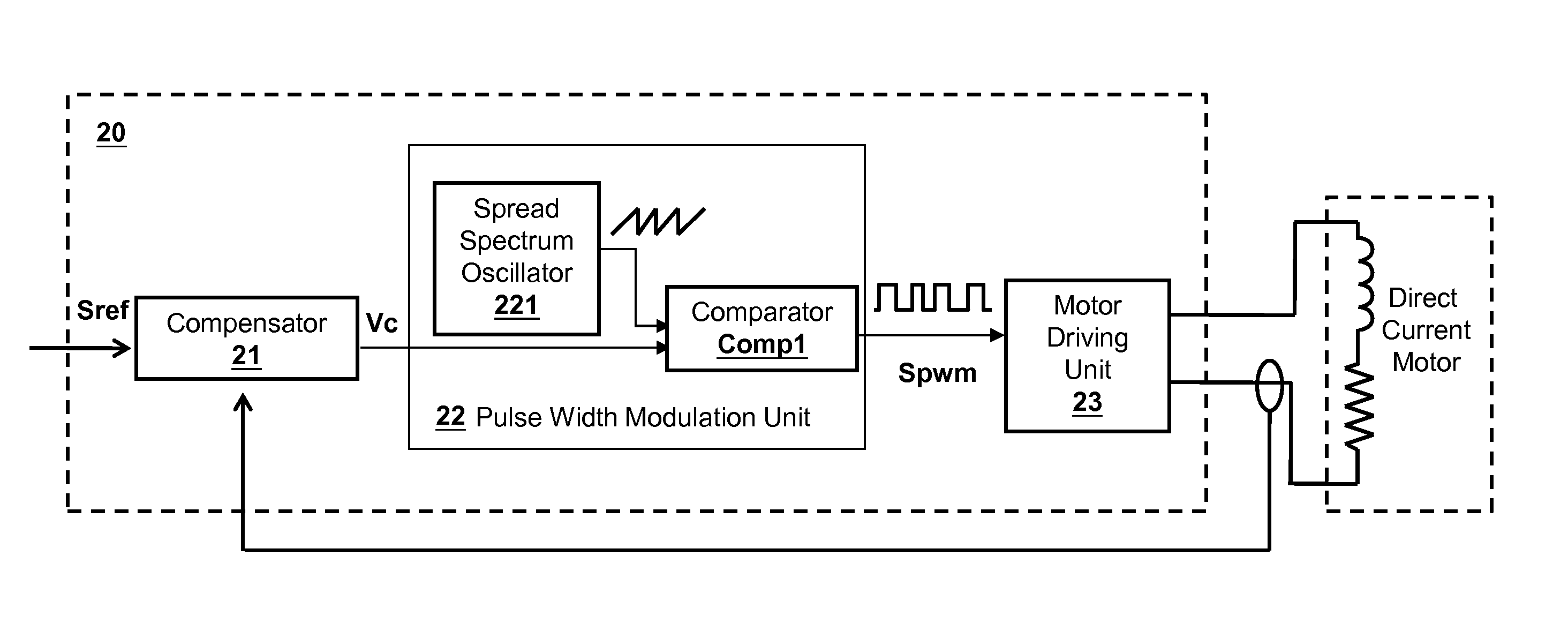
[0021]FIG. 2 shows an embodiment of the motor controller 20 according to the present invention, which includes a compensator 21, a pulse width modulation unit 22, and a motor driving unit 23. The compensator 21 generates a control signal Vc according to a reference signal Sref and a sensing signal from the direct current motor, and transmits the control signal Vc to the pulse width modulation unit 22. The sensing signal for example can be, but not limited to, a current sensing signal, or a position sensing signal. The pulse width modulation unit 22 receives the control signal Vc and generates a motor control signal Sp...


PUM


Abstract

The present invention provides a motor controller for controlling a DC motor according to a reference signal. The motor controller includes a compensator, a pulse width modulation unit, and a motor driving unit. The compensator generates a control signal according to the reference signal and a sensing signal from the DC motor. The pulse width modulation unit generates a motor control signal by comparing the control signal and a ramp signal having a varying frequency. The motor driving unit receives the motor control signal and drives the DC motor according to the motor control signal.

Description

BACKGROUND OF THE INVENTION[0001]1. Field of Invention[0002]The present invention relates to a motor controller, in particular a motor controller generating a pulse width modulation (PWM) signal with a spread spectrum to reduce the generated electromagnetic interference (EMI).[0003]2. Description of Related Art[0004]Referring to FIG. 1, a prior art motor controller 10 is shown. The motor controller 10 includes a compensator 11, a pulse width modulation unit 12, and a motor driving unit 13. The compensator 11 receives a reference signal Sref and a sensing signal from an external direct current motor, and generates a control signal Vc which is sent to the pulse width modulation unit 12; the motor driving unit 13 controls the external direct current motor according to the PWM signal generated by the pulse width modulation unit 12. The high frequency band of the PWM signal generated by the pulse width modulation unit 12 could cause EMI, and the direct current motor controlled by the PWM...

Claims


Application Information

Patent Timeline
IPC IPC(8): H02P25/02
CPCH02P25/028H02P7/29
Inventor CHANG, WEI-HSUWANG, JO-YUCHI, JEN-HUNG
Owner RICHTEK TECH