Monolithically integrated implantable flexible antenna for electrocorticography and related biotelemetry devices

a flexible antenna and electrocorticography technology, applied in the field of implantable sensor systems, can solve the problems of high infection risk of wired neural activity readout, uneconomically large electronics footprint and height, and battery-powered systems that require perilous and expensive surgeries for replacing discharged batteries

Active Publication Date: 2014-09-11
RGT UNIV OF CALIFORNIA
View PDF6 Cites 7 Cited by
  • Summary
  • Abstract
  • Description
  • Claims
  • Application Information

AI Technical Summary

Benefits of technology

[0012]An aspect of the present invention is a thin film antenna, monolithically integrated with an array of neural recording electrodes on a flexible polymer substrate. The structure is intended for long-term biometric data and power transfer such as but not limited to electrocorticographic neural recording in a wireless brain-machine interface system. The system comprises a m

Problems solved by technology

However, current solutions for implantable antennas generally require rigid substrates such as printed circuit boards and hermetic sealing, leading to un-economically large footprint and height for the electronics.
Furthermore, wired readout of neural activity poses a high infection risk and is hence o

Method used


Image

  • Monolithically integrated implantable flexible antenna for electrocorticography and related biotelemetry devices
  • Monolithically integrated implantable flexible antenna for electrocorticography and related biotelemetry devices
  • Monolithically integrated implantable flexible antenna for electrocorticography and related biotelemetry devices

Examples


Embodiment Construction

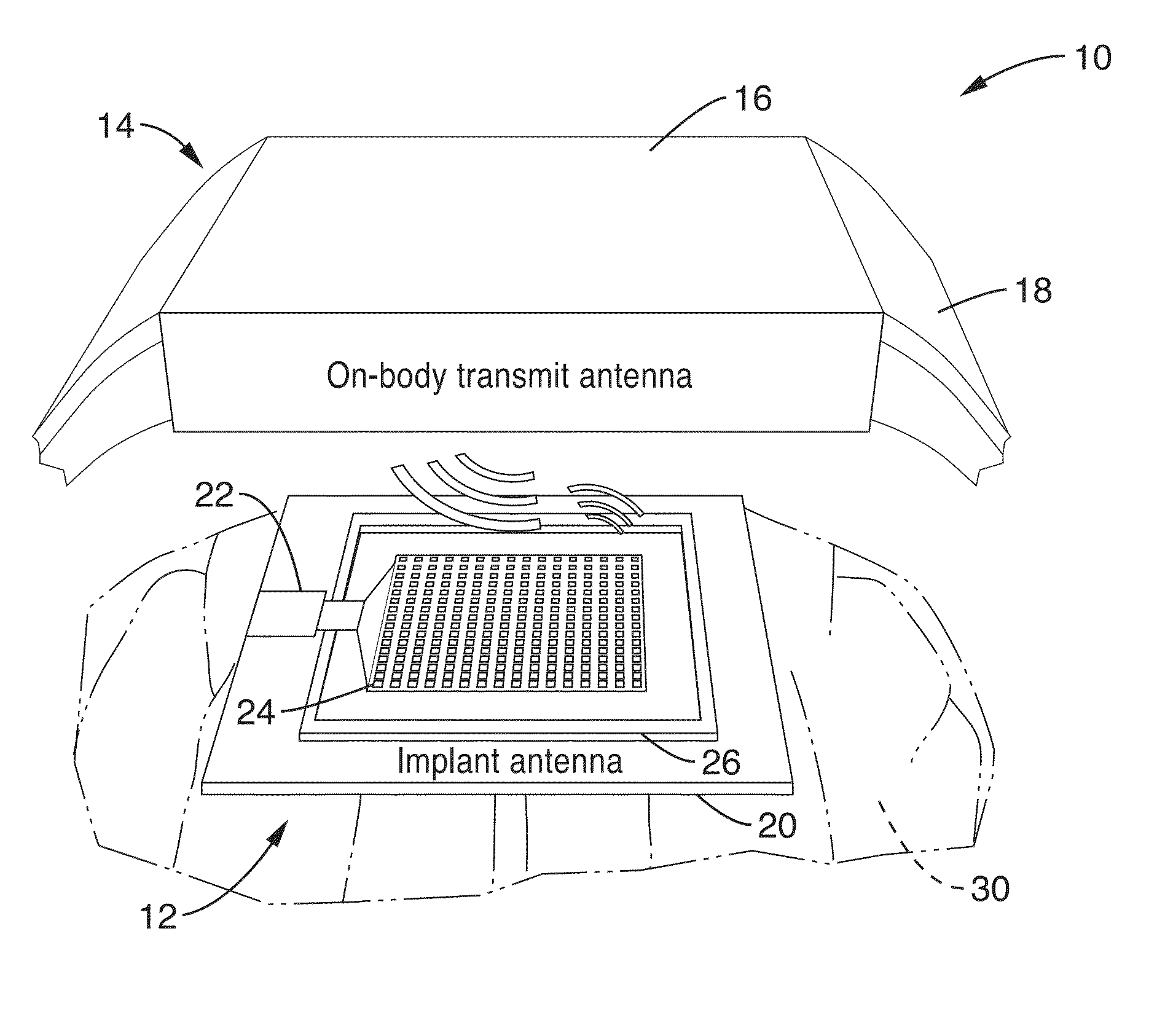
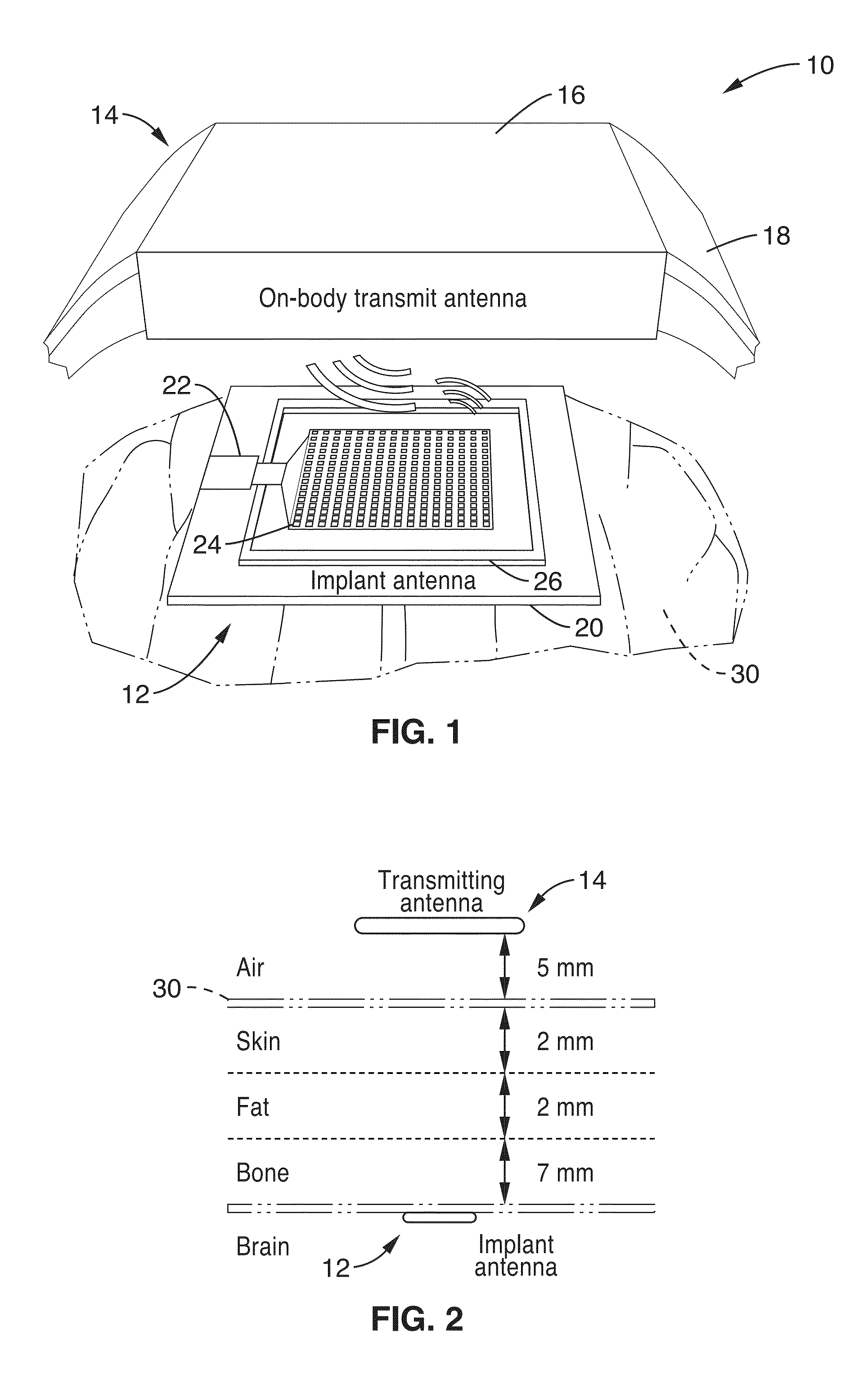
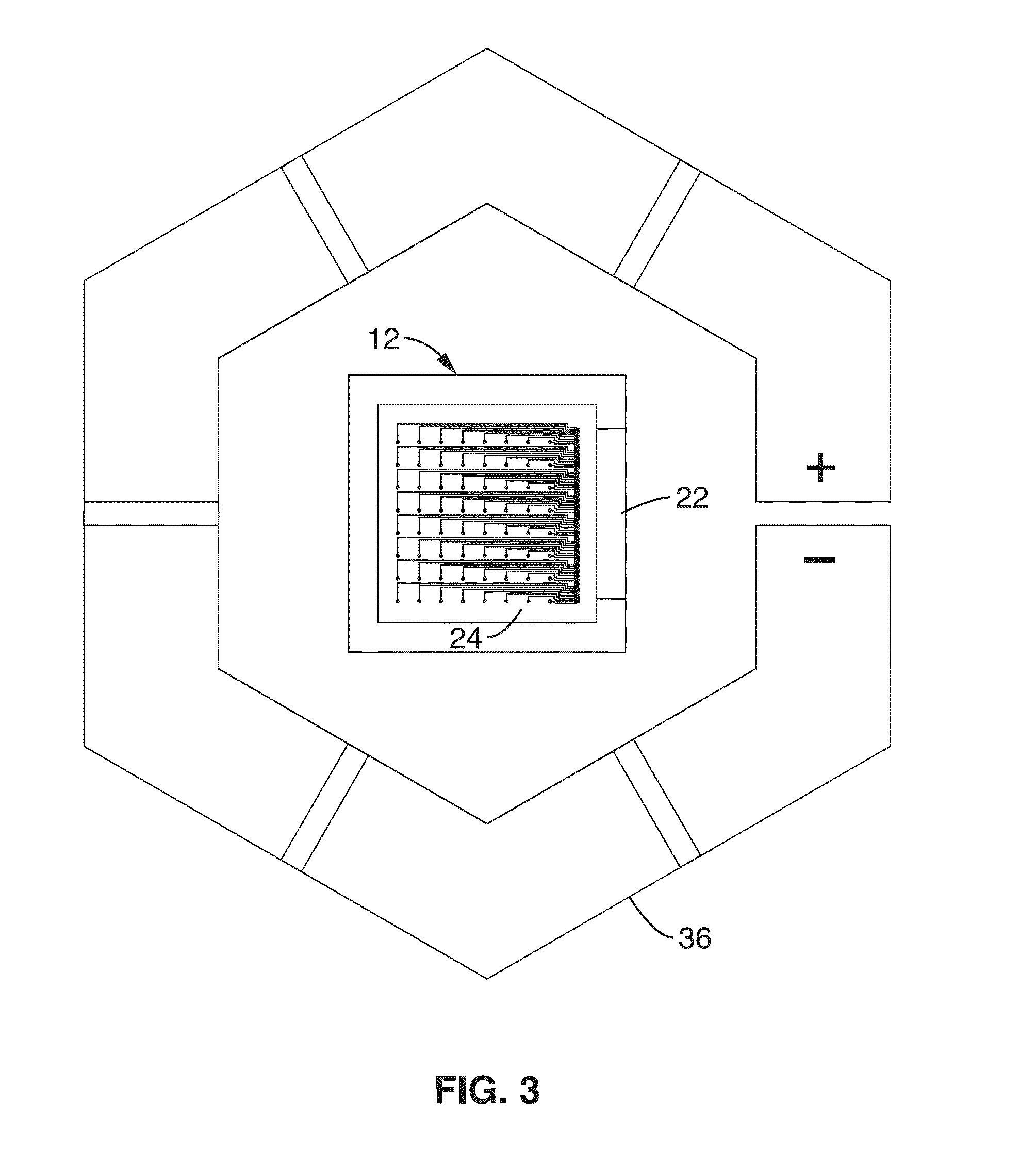
[0029]FIG. 1 is a schematic view of wireless brain-machine interface (BMI) system 10 comprising a wireless implant 12 and external reader 14 in accordance with the present invention. The implant 12 generally comprises the following components monolithically integrated onto or within the same flexible substrate 20: (a) an array of one or more electrodes 24 for the acquisition of bioelectric (e.g. neural) signals; (b) active electronics / circuitry 22 to amplify, process and transmit signals relating to one or more physiological characteristics of the patient; and (c) an antenna 26 for power delivery and data transmission between the implant 12 disposed within tissue 30 of body of a patient and the external reader 14 located external to the patient.

[0030]Thus, the electrode array 24 circuitry 22 and antenna 26 all form one monolithically integrated device. For purposes of this description, a “monolithically integrated device” is herein defined as a device having components that are intr...


PUM


Abstract

A sub-skin-depth (nanoscale metallization) thin film antenna is shown that is monolithically integrated with an array of neural recording electrodes on a flexible polymer substrate. The structure is intended for long-term biometric data and power transfer such as electrocorticographic neural recording in a wireless brain-machine interface system. The system includes a microfabricated thin-film electrode array and a loop antenna patterned in the same microfabrication process, on the same or on separate conductor layers designed to be bonded to an ultra-low power ASIC.

Description

CROSS-REFERENCE TO RELATED APPLICATIONS[0001]This application claims the benefit of U.S. provisional patent application Ser. No. 61 / 776,416 filed on Mar. 11, 2013, incorporated herein by reference in its entirety.STATEMENT REGARDING FEDERALLY SPONSORED RESEARCH OR DEVELOPMENT[0002]Not ApplicableINCORPORATION-BY-REFERENCE OF COMPUTER PROGRAM APPENDIX[0003]Not ApplicableNOTICE OF MATERIAL SUBJECT TO COPYRIGHT PROTECTION[0004]A portion of the material in this patent document is subject to copyright protection under the copyright laws of the United States and of other countries. The owner of the copyright rights has no objection to the facsimile reproduction by anyone of the patent document or the patent disclosure, as it appears in the United States Patent and Trademark Office publicly available file or records, but otherwise reserves all copyright rights whatsoever. The copyright owner does not hereby waive any of its rights to have this patent document maintained in secrecy, includin...

Claims


Application Information

Patent Timeline
IPC IPC(8): H01Q1/27A61B5/04A61B5/00
CPCH01Q1/273A61B5/04001A61B5/6868A61B5/002A61B5/0031A61B2562/028A61B5/24H01Q1/2225H01Q7/00
Inventor MULLER, RIKKYLEDOCHOWITSCH, PETER
Owner RGT UNIV OF CALIFORNIA
Why Eureka
Try Eureka