Apparatus and method for gas-liquid separation

a gas-liquid separation and apparatus technology, applied in separation processes, auxillary pretreatment, borehole/well accessories, etc., can solve the problems of inability to process flow streams with high volumes inability to accurately measure the transfer fuel, and prior art separators with limited capacity to achieve high volume and/or high flow rates. achieve the effect of effective separation, efficient and reliable operation

Active Publication Date: 2014-09-18
HAVEN TECH SOLUTIONS LLC
View PDF7 Cites 21 Cited by
  • Summary
  • Abstract
  • Description
  • Claims
  • Application Information

AI Technical Summary

Benefits of technology

[0006]One aspect of the invention relates to shaping multi-phase mixed flow using a curvilinear flow line formed in multiple loops or coils prior to separation of a fluid component from the flow path. Shaping the multi-phase flow into a curvilinear path will allow centrifugal force to more readily force the heavier, denser liquid to the outside or outer diameter wall of the flow shaping line in the curved path and allow the lighter, less dense vapor or gas to flow along the inside or inner diameter wall of the flow shaping line. In certain embodiments, once a flow regime has been restructured within the flow line, the flow component collected adjacent a particular wall of the line can be removed. For example, in flow streams characterized by a larger liquid component, the gas component of a liquid-gas flow stream will collect along the inner diameter wall of the curved flow shaping line, where the gas can be drawn or driven into an exit port located on the inner wall, thereby permitting a majority, if not all, of the gas, along with a low amount of liquid, to be sent to a conventional gas-liquid separator. The separated fluid will have a comparatively higher ratio of gas to liquid than the primary flow stream in the flow line, but will pass into the conventional gas separator at a flow rate much lower than the total flow rate within the flow shaping line. This permits for efficient separation of the gas from the liquid with the use of a smaller, more economical conventional gas-liquid separator than what would have been required for the full flow stream and / or higher flow rates.
[0010]Additionally, a fluid guiding surface may be placed on the inner wall of the flow shaping line at the exit port to further aid in directing the gas to flow to the conventional gas separator.
[0011]Furthermore, the liquid return from the conventional gas-liquid separator may be arranged in close downstream proximity to the exit port on the inner wall of the flow shaping line. The close proximity of the liquid return and the exit port allows the use of a venturi, nozzle or other restriction located adjacent the liquid return in the flow shaping line just downstream of the exit port. The venturi, nozzle or other restriction accelerates the velocity of the liquid in flow shaping line as it flows across the exit port. This acceleration of the liquid helps to pull the liquid out of the conventional gas-liquid separator. In addition, the acceleration of the liquid within the flow shaping line helps to prevent any solids that may be present in the gas-liquid flow from entering the exit port and it helps to lower the amount of liquid that enters the exit port and thus enters the conventional separator.
[0016]The invention therefore allows a multi-phase fluid to be effectively separated with the use of a smaller conventional separator than was previously possible. The invention accomplishes this without using additional complex mechanical devices and thus will operate efficiently and reliably.

Problems solved by technology

If a kick is not quickly controlled, it can lead to a blow out.
Often times, however, prior art separators, have limited capability to process flow streams with high volumes and / or high flow rates, such as those characteristic of wellbores.
For example, when supplying fuel to ships, known as bunkering, air is often entrained in the fuel, causing an inaccurate measurement of the transferred fuel.
In this regard, entrained gasses can prevent the accurate measurement of a liquid product, whether it is fuel transferred during bunkering or a liquid flowing in a pipeline.

Method used


Image

  • Apparatus and method for gas-liquid separation
  • Apparatus and method for gas-liquid separation
  • Apparatus and method for gas-liquid separation

Examples


Embodiment Construction

[0031]In the detailed description of the invention, like numerals are employed to designate like parts throughout. Various items of equipment, such as pipes, valves, pumps, fasteners, fittings, etc., may be omitted to simplify the description. However, those skilled in the art will realize that such conventional equipment can be employed as desired.

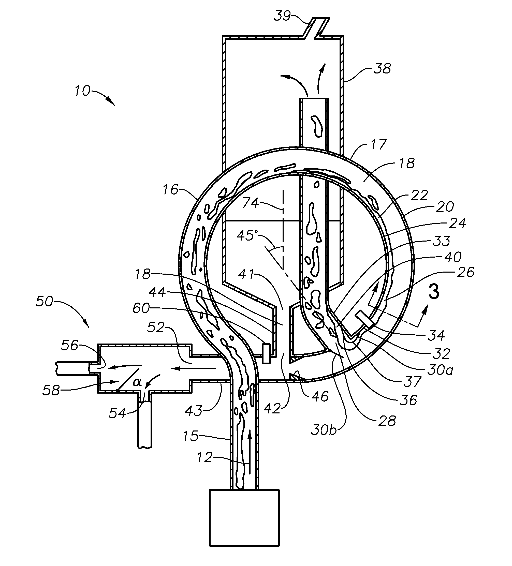
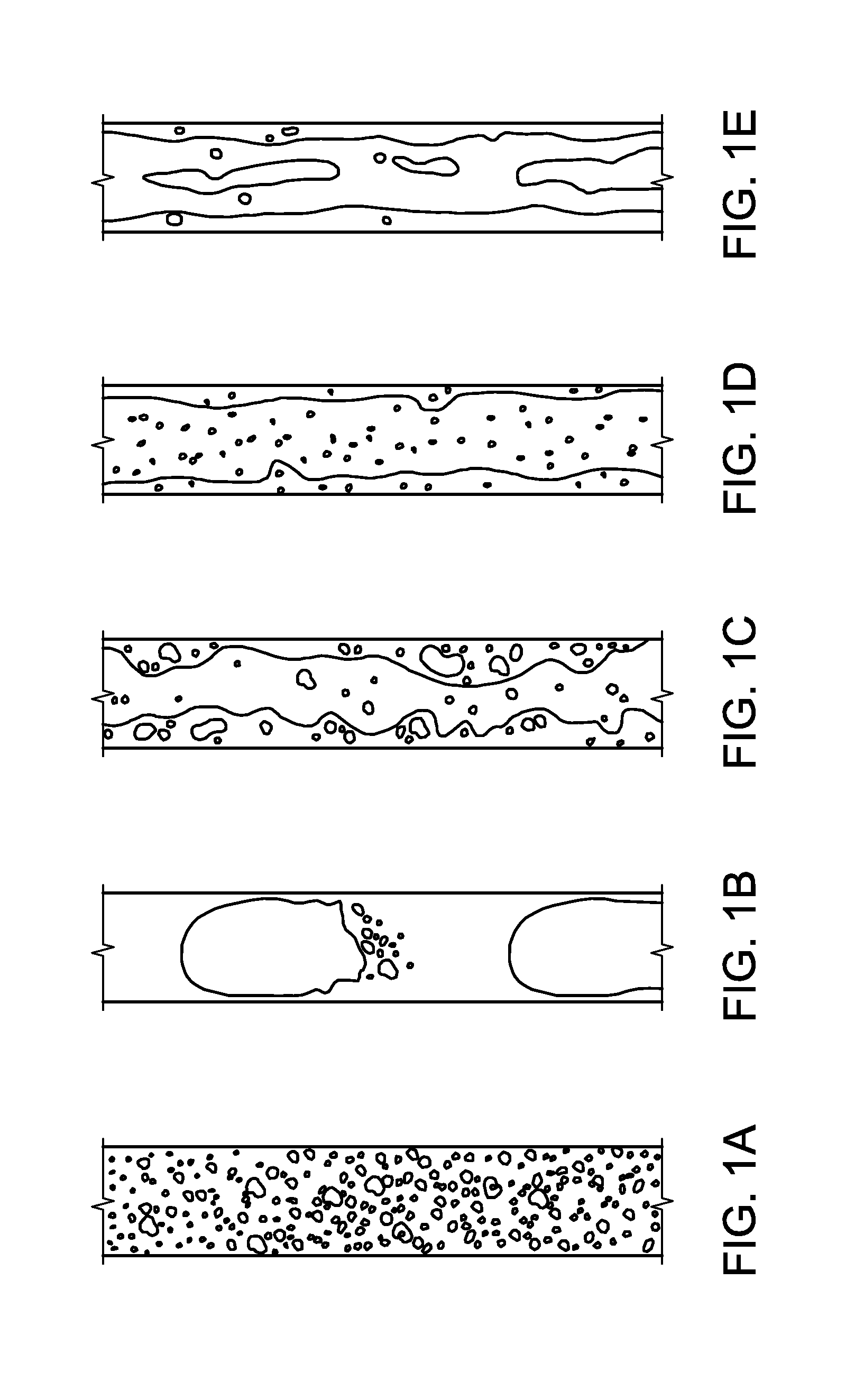
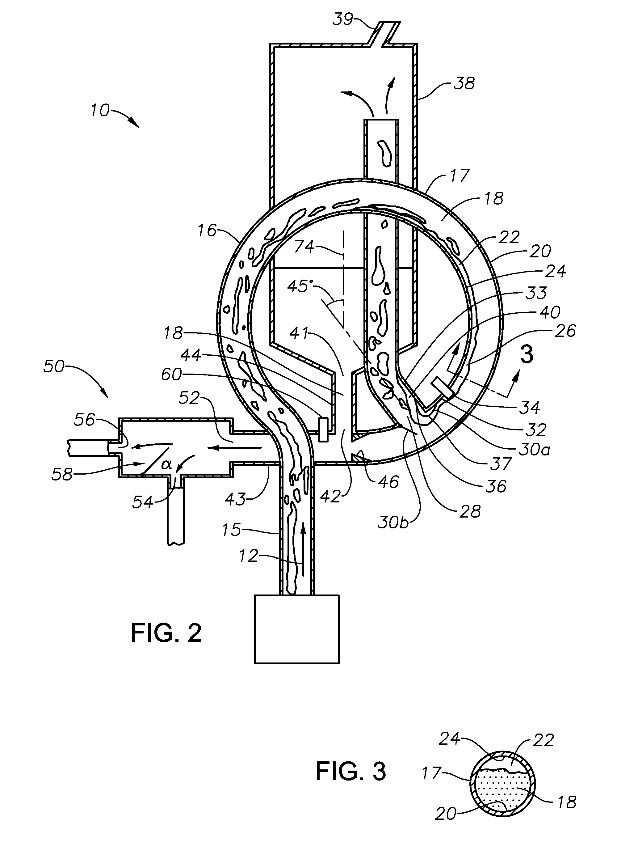
[0032]FIG. 2 illustrates a cross-sectional view of an embodiment of a separation apparatus 10. In an exemplary embodiment, the separation apparatus 10 is in fluid communication with a main flow line 15 in which a multi-phase flow 12 is traveling. The multi-phase flow 12 could be any type of multiphase gas-liquid flow regime or flow pattern, such as, for example, bubble flow, slug or plug flow, churn flow, annular flow or wispy annular flow. Moreover, the multi-phase flow may include two components within a single phase, such as water and oil within the liquid phase. The multi-phase flow 12 within main line 15 is directed into a curvilinea...


PUM

PropertyMeasurementUnit
diameteraaaaaaaaaa
diametersaaaaaaaaaa
shapeaaaaaaaaaa

Abstract

A multi-phase separation apparatus shapes fluid flow in a flow shaping line preferably shaped to have a plurality of loops with consecutively decreasing diameters. Shaping the two-phase flow drives the heavier, denser fluids to the outside wall of the flow shaping line and allows the lighter, less dense fluids such as gas to occupy the inner wall of the flow shaping line. With the gas positioned on the inner wall, an exit port on the inner wall permits a majority, if not all, of the gas, along with a minimal amount of liquid, to be diverted to a conventional gas-liquid separator at a flow rate much lower than the total flow rate within the flow shaping line. The remaining liquid flow in the flow shaping line is subsequently introduced into an adjustable phase splitter to separate different liquid components from one another.

Description

FIELD OF THE INVENTION[0001]The present invention generally relates to the separation of components in a multi-phase flow stream. More specifically, it relates to restructuring flow regimes by a flow shaping apparatus so that the majority of a particular fluid component in a flow stream is located in a certain area of the flow stream, which allows for effective separation of the various fluid components.BACKGROUND OF THE INVENTION[0002]A gas-liquid two phase flow stream includes a mixture of different fluids having different phases, such as air and water, steam and water, or oil and natural gas. Moreover, the liquid phase of a fluid flow stream may further comprise different liquid components, such as oil and water. A gas-liquid two phase flow takes many different forms and may be classified into various types of gas distribution within the liquid. These classifications are commonly called flow regimes or flow patterns and are illustrated in FIGS. 1A-1E. Bubble flow as illustrated i...

Claims


Application Information

Patent Timeline
Patent Type & Authority Applications(United States)
IPC IPC(8): B01D19/00E21B21/06B65D88/76
CPCB01D19/0042E21B21/067B65D88/76B01D53/00B01D19/0063
Inventor ELMS, DAVID JAMESHUDSPETH, GREGORY ALLEN
Owner HAVEN TECH SOLUTIONS LLC
Why Eureka
Try Eureka