Substrate processing apparatus

a processing apparatus and substrate technology, applied in vacuum evaporation coatings, chemical vapor deposition coatings, coatings, etc., can solve the problems of increasing the amount of deposits generated onto the inner wall of the chamber, cumbersome design, and affecting the other processing properties of the substrate, so as to reduce the attachment of particles generated and facilitate the adjustment of pressure

Active Publication Date: 2014-09-18
CANON ANELVA CORP
View PDF22 Cites 10 Cited by
  • Summary
  • Abstract
  • Description
  • Claims
  • Application Information

AI Technical Summary

Benefits of technology

[0016]The present invention makes it possible to reduce attachment of particles generated in a processing space to an inner wall of a chamber in which the processing space is formed, and to easily adjust pressure in the substrate processing space while introducing a gas into the substrate processing space at a desired flow race.

Problems solved by technology

Meanwhile, pressure in the processing space can also affect other processing properties of the substrate.
However, it is very cumbersome to design the gap between members such as the shields each time according to the substrate processing to carry out.
Moreover, too large gap increases the amount of deposits generated onto the inner wall of the chamber.
However, there remain problems to be solved.

Method used


Image

  • Substrate processing apparatus
  • Substrate processing apparatus
  • Substrate processing apparatus

Examples


first embodiment

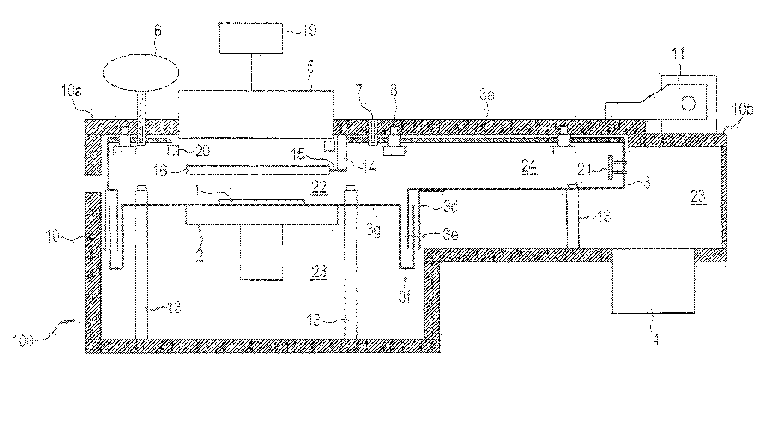
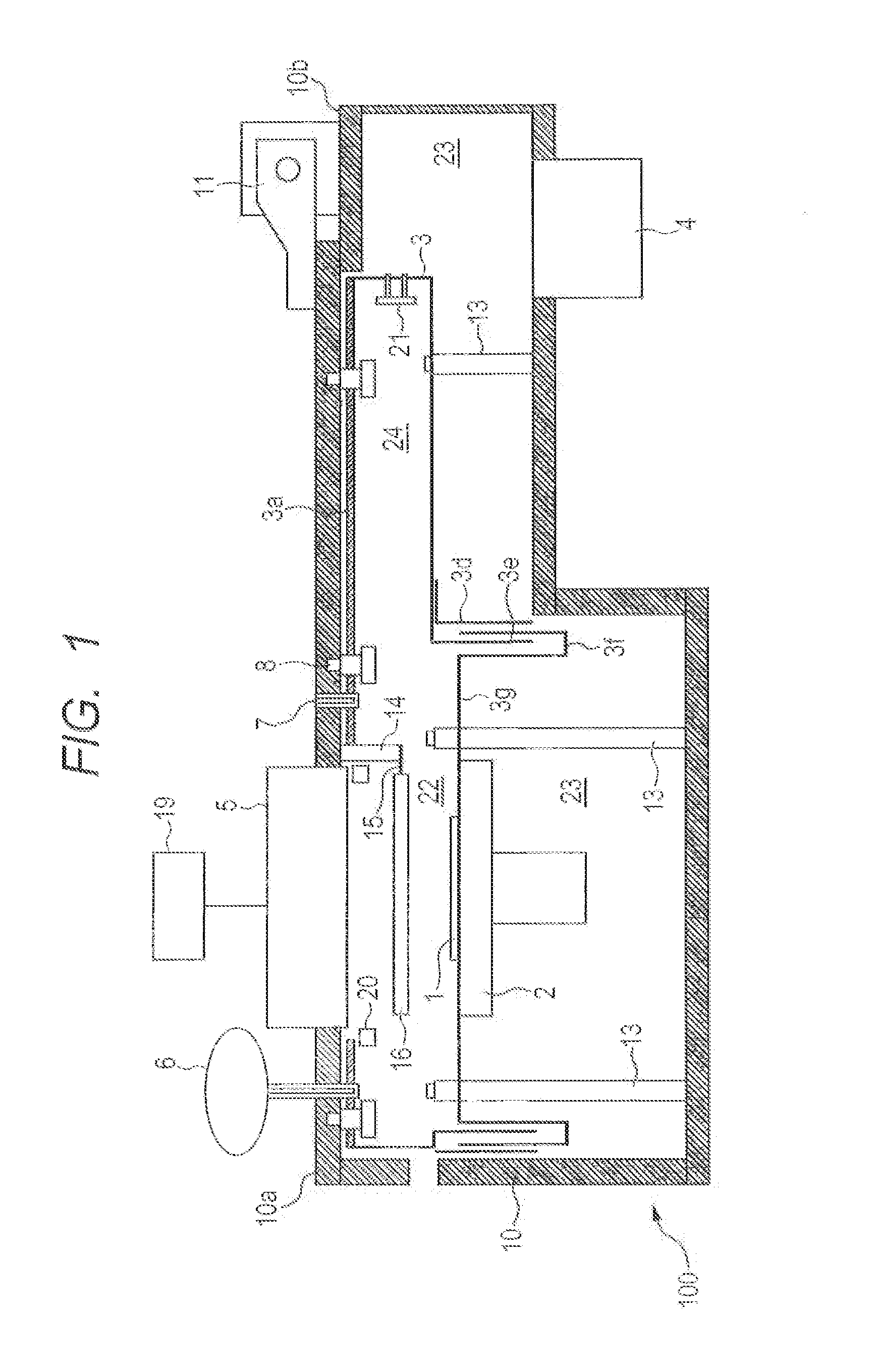
[0037]FIG. 1 shows a sputtering apparatus as one embodiment of a vacuum processing apparatus (substrate processing apparatus) according to the present invention. FIG. 1 is an overall schematic diagram of a sputtering apparatus 100.

[0038]As shown in FIG. 1, the sputtering apparatus 100 has a chamber 10 as a vacuum container, a chamber ceiling wall 10b, a chamber top lid 10a, and a hinge portion 11. The chamber 10 can be opened by the top lid 10a attached to the hinge portion 11, exposing an internal space thereof. The chamber 10 includes a target, holder 5 configured to retain a target, and an exhaust portion 4, such as a vacuum pump, configured to exhaust a gas in the chamber 10. The target holder 5 is connected to a voltage applying portion 19, and functions as a cathode. Around the target holder 5 as a cathode, a target ring 20 is provided as an anode, surrounding a target retained on the target holder 5 (a target retaining surface). The target ring 20 is grounded. With such a con...

second embodiment

[0057]A second embodiment of the present invention is described next with reference to FIGS. 5A and 5B.

[0058]FIG. 5A is a diagram illustrating an exhaust portion 21 according to this embodiment, and FIG. 5B is a sectional view taken along arrowed line VB-VB in FIG. 5A.

[0059]In this embodiment, the shade 31 has a second protruding portion 33 at an outer circumferential portion thereof, the second protruding portion 33 protruding toward the shield 3. The second protruding portion 33 and the first protruding portion 30 hare a predetermined gap 51 therebetween, and the gap 51 and the gaps 30c communicate. Thus, in this embodiment, the communication path is constituted by the gap 51, the gaps 30c, the hollow portion 30d, and the opening portion 3a.

[0060]FIG. 6 shows the exhaust portion 21 according to this embodiment from the processing space 22 side to illustrate positional relations of the members. The surface 30a of the first protruding portion 30 is in contact with the shade 31, and...

third embodiment

[0061]A third embodiment is described next with reference to FIG. 7.

[0062]In this embodiment, the first protruding portion 30 and the shade 31 are not in contact, and insertion members 34 are inserted between the first protruding portion 30 and the shade 31. The first protruding portion 30 is uniform in height throughout, unlike the embodiments described above. By the insertion members 34 placed at affixed portions between the first protruding portion 30 and the shade 31, gaps are formed at portions other than the affixed portions. As tire insertion member 34, anything functioning as a spacer, such as a washer for example, can be used. In this embodiment, the insertion member 34 is a spacer configured to be able to change the position of the shade 31 relative to the first protruding portion 30. Such a spacer includes a washer.

[0063]In this embodiment, by using a washer as the insertion member 34, when the shade 31 is to be affixed to the first protruding portion 30 with the screws 3...


PUM

PropertyMeasurementUnit
areaaaaaaaaaaa
distanceaaaaaaaaaa
plasmaaaaaaaaaaa

Abstract

The present invention provides a vacuum processing apparatus capable of reducing attachment of particles generated in a processing space to an inner wall of a chamber, and of easily adjusting pressure in the processing space while introducing a gas into the processing space at a desired flow rate. A vacuum processing apparatus according to one embodiment includes: a container; a gas exhaust portion; a substrate holder configured to retain a substrate; a shield provided to surround the substrate holder and dividing an inside of the container into a processing space and an outside space; a gas introducing portion; a plasma generating portion; and an exhaust portion provided to the shield having a communication path through which the processing space and the outside space communicate, wherein at least part of the communication path is hidden from a region where the plasma generating portion generates the plasma.

Description

CROSS-REFERENCES TO RELATED APPLICATIONS[0001]This application is a continuation application of International Application No. PCT / JP2012 / 008132, filed Dec. 19, 2012, which claims the benefit of Japanese Patent Application No. 2011-281015, filed Dec. 22, 2011. The contents of the aforementioned applications are incorporated herein by reference in their entireties.TECHNICAL FIELD[0002]The present invention relates to a substrate processing apparatus, and more specifically, relates to a substrate processing apparatus that forms a film by introducing a predetermined gas into a processing space.BACKGROUND ART[0003]Vacuum processing apparatuses that perform various kinds of substrate processing under vacuum, such as film formation and etching, are widely used. As shown in Patent Document 1, shields are provided on an inner wall of a vacuum processing apparatus to prevent a film-forming substance which is also deposited on a portion other than a substrate during film formation or an etchin...

Claims


Application Information

Patent Timeline
Patent Type & Authority Applications(United States)
IPC IPC(8): C23C16/455
CPCC23C16/45589C23C14/564C23C16/4401
Inventor NAKAZAWA, TOSHIKAZUTSUKAMOTO, NORIHITOUEDA, KEISUKEOZAKI, EIJI
Owner CANON ANELVA CORP
Why Eureka
Try Eureka