Method and apparatus for fabrication and repair of thermal barriers

a technology of thermal barrier and fabrication method, applied in the direction of water setting substance layered product, machine/engine, fastening means, etc., can solve the problems of reducing the thermal protection of the ring segment, reducing engine power and efficiency, and losing clearance control

Inactive Publication Date: 2014-09-18
SIEMENS ENERGY INC
View PDF5 Cites 31 Cited by
  • Summary
  • Abstract
  • Description
  • Claims
  • Application Information

AI Technical Summary

Problems solved by technology

This can increase spalling of the coating causing loss of clearance control, which reduces engine power and efficiency.
It also reduces thermal protection of the ring segment, reducing its service life.
Another cause for spalling is increased hardness of the abradable coating through gradual sintering during engine operation.
This is expensive, energy-intensive, and time-consuming.

Method used


Image

  • Method and apparatus for fabrication and repair of thermal barriers
  • Method and apparatus for fabrication and repair of thermal barriers
  • Method and apparatus for fabrication and repair of thermal barriers

Examples


Embodiment Construction

[0018]The inventors realized that damage to a ring segment thermal barrier coating is often localized to particle impact points and to the spalled rub swath of the blade tip, and that localized repair could extend the life of the ring segment at minimal cost. An apparatus and method for accomplishing such a novel repair is disclosed herein.

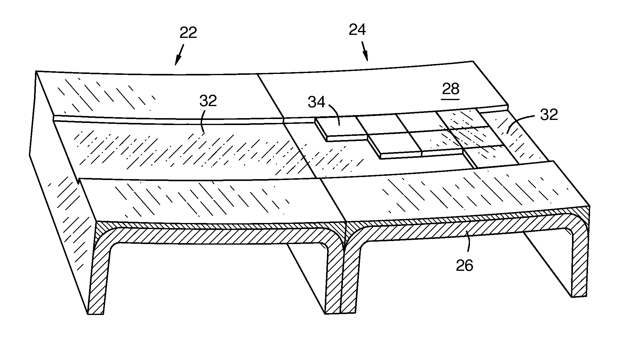
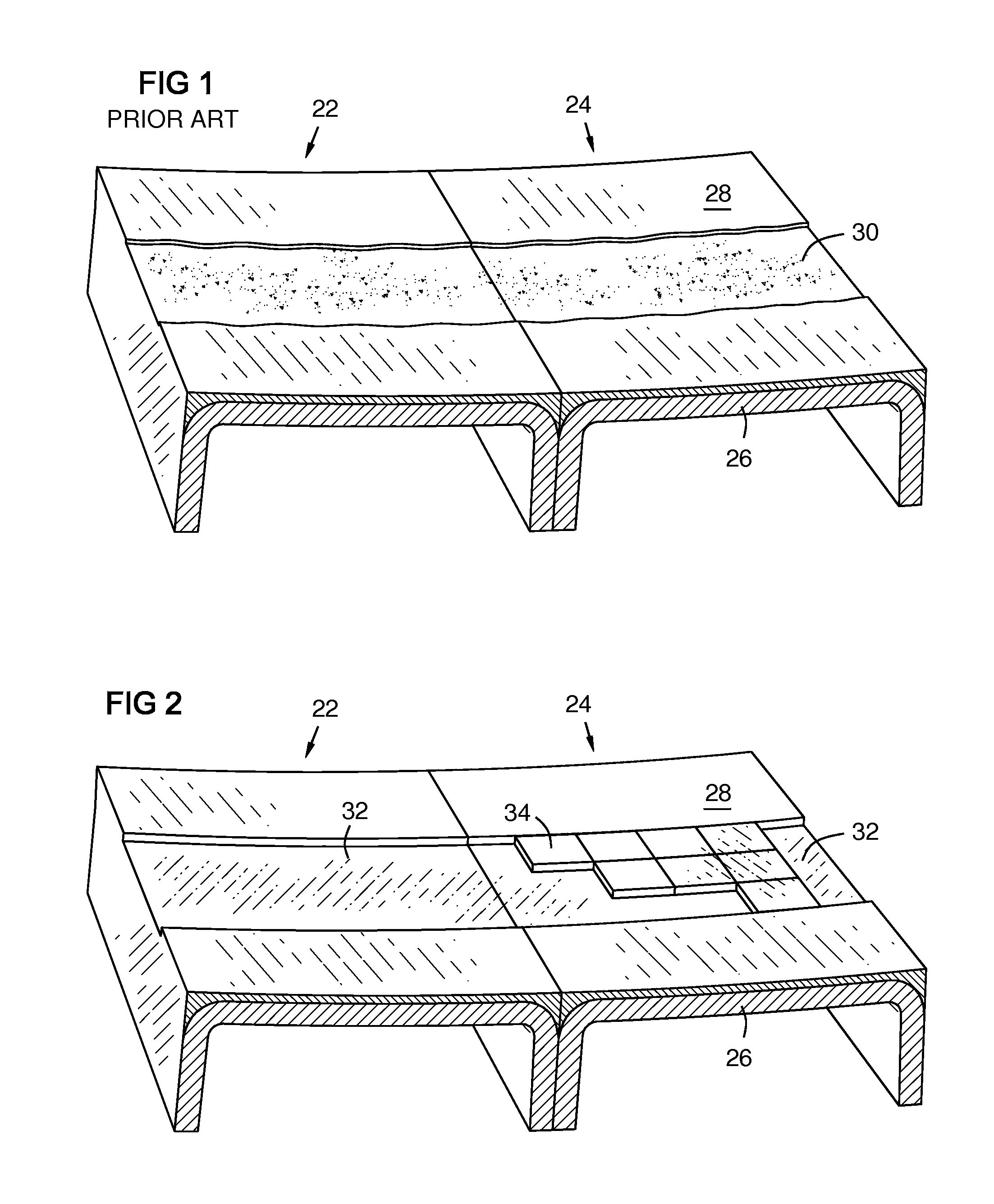
[0019]FIG. 1 shows two adjacent shroud ring segments 22, 24. Each segment includes a substrate 26 and a thermal barrier coating (TBC) 28. A turbine blade tip swath 30 has been worn into the thermal barrier coating. This swath enlarges and degrades over time, resulting in loss of turbine efficiency due to the hot gas flowing over the tip of the blade rather than across its airfoil.

[0020]FIG. 2 shows the two adjacent shroud ring segments 22, 24 with a portion 32 of the worn TBC 28 encompassing the swath 30 of FIG. 1 removed down to the substrate 26. Thermal barrier tiles 34 are being installed as described herein. The surface of the substrate may be...


PUM

PropertyMeasurementUnit
particle sizeaaaaaaaaaa
material propertyaaaaaaaaaa
temperatureaaaaaaaaaa

Abstract

A thermal barrier tile (34) with a braze layer (46) co-sintered to a ceramic layer (48) is brazed to a substrate (26) of a component for fabrication or repair of a thermal barrier coating (28) for example on a gas turbine ring segment (22, 24). The tile may be fabricated by disposing a first layer of a metal brazing material in a die case (40); disposing a second layer of a ceramic powder on the metal brazing material; and co-sintering the two layers with spark plasma sintering to form the co-sintered ceramic / metal tile. A material property of an existing thermal barrier coating to be repaired may be determined (90), and the co-sintering may be controlled (93) responsive to the property to produce tiles compatible with the existing thermal barrier coating in a material property such as thermal conductivity.

Description

FIELD OF THE INVENTION[0001]The invention relates generally to thermal barrier coatings, and in one embodiment, to the fabrication and repair of thermal barrier coatings on gas turbine engine components.BACKGROUND OF THE INVENTION[0002]The turbine section of a gas turbine engine contains a stationary shroud ring around each stage or row of rotating blades. A shroud ring has a sealing surface with close clearance to the blade tips to reduce inter-stage gas leakage past the turbine blade tips. The shroud ring is formed of curved segments called ring segments or blade outer air seals. Turbine blades and ring segments are commonly made of high temperature superalloys based on nickel, cobalt, or nickel-iron that maintain mechanical strength, creep resistance, surface stability, and corrosion / oxidation resistance at high temperatures. The sealing surface of each ring segment is typically coated with an oxidation resistant metallic bond coat and a thermally insulating ceramic thermal barri...

Claims


Application Information

Patent Timeline
Patent Type & Authority Applications(United States)
IPC IPC(8): B23P6/00
CPCB23P6/005B23K1/0018B22F3/105B22F5/009B23K35/3033C23C26/00B23K35/0244F01D5/005B23K2201/001F05B2230/80F05B2230/90B23K35/304F01D11/08F05D2230/30F05D2230/80F01D11/122F05D2240/11B22F7/02B23K1/008Y10T428/24612B23K35/02B23K35/0222Y10T428/249961C22C19/03C22C19/058C22C19/056B23K2101/001B23K1/0012B22F7/062B22F7/06B22F5/04F01D5/284
Inventor KULKARNI, ANAND A.KAMEL, AHMEDLAMPENSCHERF, STEFANSHIPPER, JR., JONATHAN E.SCHILLIG, CORAMERRILL, GARY B.
Owner SIEMENS ENERGY INC
Why Eureka
Try Eureka