Reducing incremental measurement sensor error

a technology of incremental measurement and sensor error, which is applied in the field of minimally invasive procedures, can solve the problems of unanticipated or unmodeled constraints imposed by the patient's anatomy, the parameters of the tool do not meet the ideal/anticipated parameters, and the catheter's motion does not match the actual motion of the catheter, etc., and achieves the effect of reducing measurement error

Active Publication Date: 2014-09-18
AURIS HEALTH INC
View PDF2 Cites 82 Cited by
  • Summary
  • Abstract
  • Description
  • Claims
  • Application Information

AI Technical Summary

Benefits of technology

[0008]Exemplary systems and methods are disclosed for reducing measurement error, e.g., relating to position measurements of an elongated member, e.g., along a distal portion of the elongated member. An exemplary method includes providing an incremental sensor measurement at a distal position on an elongated member, and applying registration data at one or more proximal locations along the elongated member. This exemplary method may further include determining a position of the incremental measurement sensor based at least upon the registration data from the one or more proximal locations.

Problems solved by technology

However, at times the assumed motion of the catheter does not match the actual motion of the catheter.
One such reason for this issue is the presence of unanticipated or unmodeled constraints imposed by the patient's anatomy.
Another reason for this may be that the parameters of the tool do not meet the ideal / anticipated parameters because of manufacturing tolerances or changes in the mechanical properties of the tool from the environment and aging.
One drawback of IMSs is that a measurement noise (error) at any location along the path may propagate to all measurements distal to that measurement.
While these errors are implicit in the nature of the sensor, orientation errors at a proximal portion of the IMS may result in a large position error at the distal end of the elongate member.
In applications that include accurate distal position measurements, this can cause the measured tip position to vary greatly between successive measurements due to noise at a single point in the proximal portion.
The longer the lever arm, the more pronounced the conversion from proximal orientation error to distal position error.
Thus, for Incremental Measurement Sensors that build a shape using a sequence of small orientation measurements, a small error in orientation at the proximal end of the sensor will cause a large error in position at distal points on the fiber.
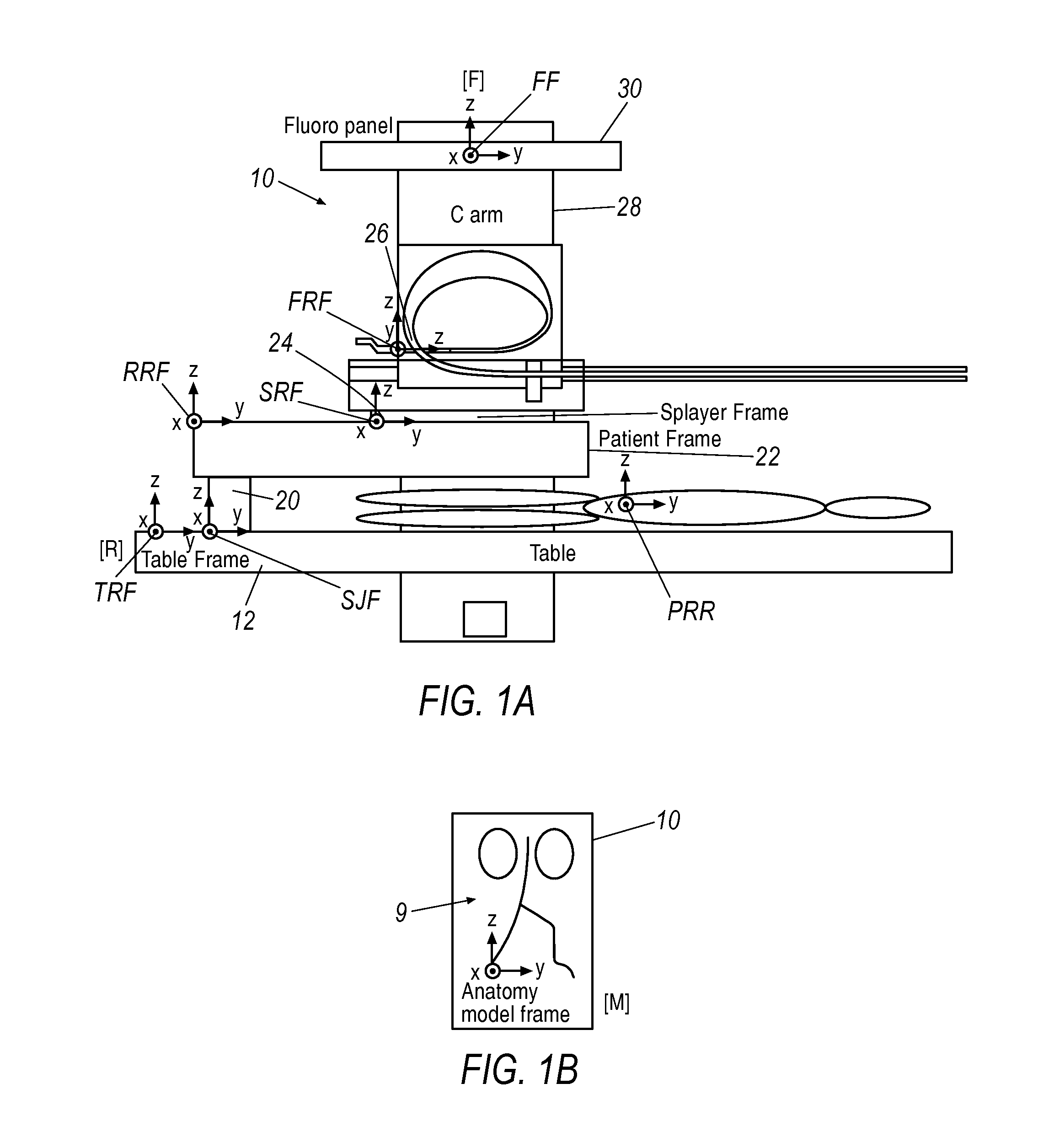
For incremental measurement sensors, such registration is challenging because the coordinate system or frame of the sensor is not always easily related to the coordinate system of interest (i.e., the pre-operative 3D model).
Due to the variability in equipment used in a clinical environment, in certain situations there may be no guarantee that such information will be available or easily obtainable to an outside party.
However, this technique will require some image segmentation (to identify and separate out targeted shapes).
However, if the patient moves, even slightly, the 3D Model could be mis-registered.
However, the correlation may return many local maxima since the tool configuration may follow many different paths between fixed distal and proximal ends.
Choosing an incorrect maximum introduces registration error.
Such situations also may lead to registration error.
Differences over a large time constant (seconds) may lead to changes in the model's warping parameters.
However, the accuracy of this registration procedure can be difficult and inadequate for applications that require sub-mm accuracy at the distal end of the sensor.
Inaccuracy will result if the origin of the IMS moves; if the origin does move, it needs to be tracked in the world coordinate frame, which may lead to error.
In addition, the error inherent in the sensor could cause errors in the sensor measurement.
For instance, in a fiber optic shape sensor, the tighter the bends, the less accurate the sensor is.
Tight bends that may occur early in the path of the fiber either due to mechanical structures in the device or pathways in the anatomy, cause additional error in the orientation measurement.
This orientation error may be magnified by the lever arm of the fiber causing the tip to be inaccurate by centimeters.
This is unsuitable for many applications since sub-millimeter accuracy is desired.
This solution could be completed using many standard computer graphics matching techniques or posed as a numeric optimization problem.
Because two-dimensional imaging will provide less information than a 3D model it may not provide as much information to reduce error, but it would likely remove error at least in the plane of the image.
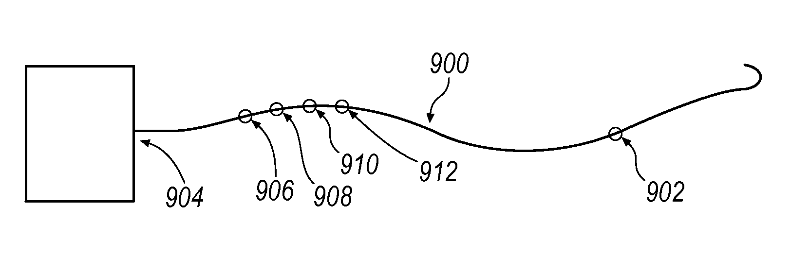
However, in these examples registering a shape to a 3D model does not necessarily completely replace the registration at the splayer (not shown in FIG. 9).
However, this algorithm can be time consuming and computationally intensive, especially when a good starting point is not given.
The above exemplary approach may be particularly advantageous for relative position display (essentially a coordinate frame not correctly registered to the fluoroscopy / anatomical coordinate frames) but may ultimately make it difficult to determine a global position of the tip of the catheter.
Thus, white noise may be present on the level of the strain / incremental orientation as opposed to the final incremented position and orientation.
This is potentially problematic because by filtering different dimensions at different rates, trajectories can become skewed, producing measurement points that do not lie along the true trajectory of the device.

Method used


Image

  • Reducing incremental measurement sensor error
  • Reducing incremental measurement sensor error
  • Reducing incremental measurement sensor error

Examples


Embodiment Construction

[0024]Exemplary approaches described herein provide full or partial registration along the length of a sensor to reduce the influence of measurement error. As will be described further below, an exemplary registration process generally relates a reference frame of a sensor to another reference frame of interest. Alternatively or in addition to examples employing full or partial registration along the length of a sensor, applying heavier filtering at the proximal end of the sensor can provide a more stable base for distal measurements reducing the influence of measurement errors. While these exemplary approaches are discussed in the context of a Fiber Optic Shape Sensing and Localization (FOSSL) system, other visualization methodologies may be employed. Fiber optic shape sensing is a technology that can sense the shape of a flexible body such as a catheter during a surgical procedure to permit visualization of the catheter in the patient's anatomy.

[0025]One exemplary methodology prov...


PUM


Abstract

For position sensors, e.g., a fiber-based system, that build a shape of an elongated member such as a catheter using a sequence of small orientation measurements, a small error in orientation at the proximal end of the sensor will cause large error in position at distal points on the fiber. Exemplary methods and systems are disclosed which may provide full or partial registration along the length of the sensor to reduce the influence of the measurement error. Additional examples are directed to applying selective filtering at a proximal end of the elongated member to provide a more stable base for distal measurements and thereby reducing the influence of measurement errors.

Description

CROSS-REFERENCE TO RELATED APPLICATIONS[0001]This application claims priority to U.S. Provisional Patent Application No. 61 / 779,742, filed Mar. 13, 2013, the contents of which are hereby incorporated in their entirety.BACKGROUND[0002]Currently known minimally invasive procedures for diagnosis and treatment of medical conditions use shapeable instruments, such as steerable devices, flexible catheters or more rigid arms or shafts, to approach and address various tissue structures within the body. For various reasons, it is highly valuable to be able to determine the 3-dimensional spatial position of portions of such shapeable instruments relative to other structures, such as the operating table, other instruments, or pertinent anatomical tissue structures. Such information can be used for a variety of reasons, including, but not limited to: improve device control; to improve mapping of the region; to adapt control system parameters (whether kinematic and / or solid mechanic parameters);...

Claims


Application Information

Patent Timeline
Patent Type & Authority Applications(United States)
IPC IPC(8): G01B11/14
CPCG01B11/14G01B21/045A61B6/12A61B6/032A61B6/485A61B6/586G01B11/24A61M25/0108A61M2025/0166A61M2205/702A61B90/39A61B2090/3966A61B5/0066A61B8/12
Inventor WALKER, SEAN P.WONG, SERENA H.PARK, JUNETANNER, NEAL A.
Owner AURIS HEALTH INC
Why Eureka
Try Eureka