


Quick Research
Generate reliable direction feasibility study reports for your R&D in just a few steps.

Technical Q&A
Discover and master advanced knowledge NOW. Basics, ideas, possibilities, all at once.

Find Solutions
As an expert in R&D theories, this can generate solutions to your technical problems instantly.

Evaluate Feasibility
Analyze your overall solution with one click, know your potential R&D risks in advance.

Monitor Landscape
Get weekly tech updates, stay abreast of the latest tech innovations and key insights.
Ionized gas detector and ionized gas detecting method
a technology of ionized gas and detector, which is applied in the direction of vacuum gauges, instruments using ionisation effects, fire alarm smoke/gas actuation, etc., can solve the problems of inability to exert functions, drop in pid, and inability to measure accurate current values, etc., to achieve high detection sensitivity and cancel the effect of parasitic capacitance between the electrodes
- Summary
- Abstract
- Description
- Claims
- Application Information
AI Technical Summary
Benefits of technology
Problems solved by technology
Method used
Image

Examples
first embodiment
[0033]an ionized gas detector according to the present invention will hereinafter be described, referring to drawings.
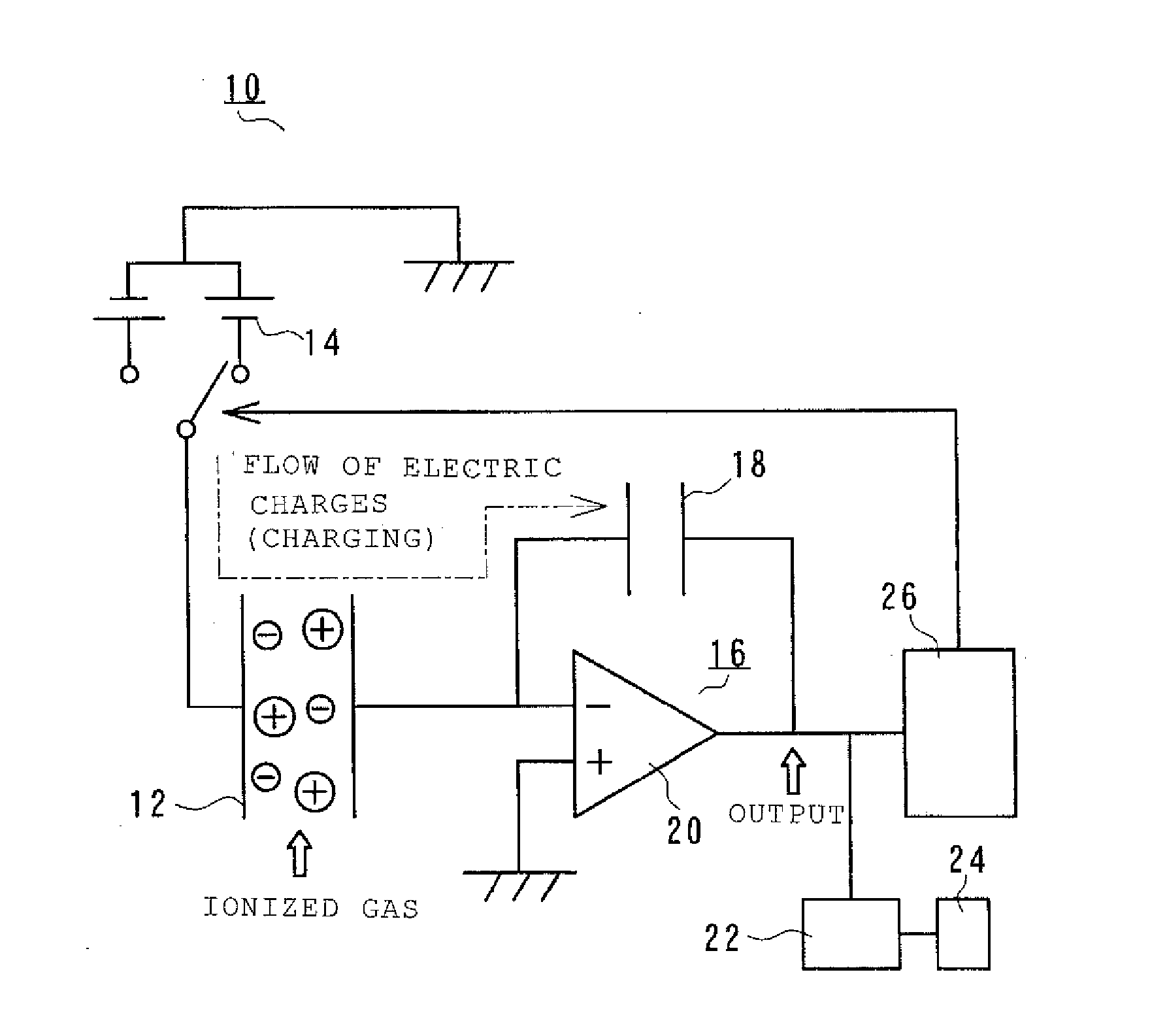
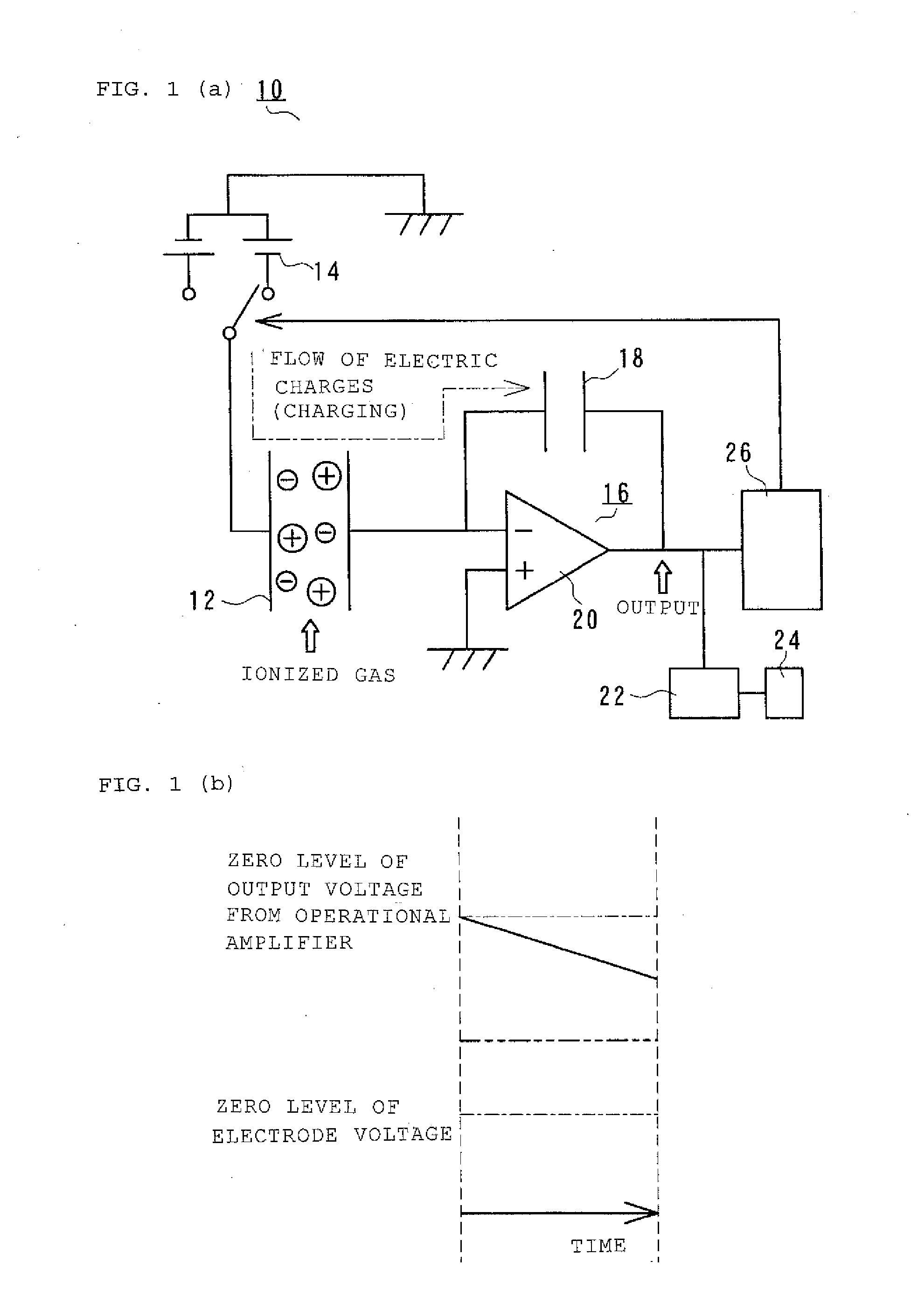
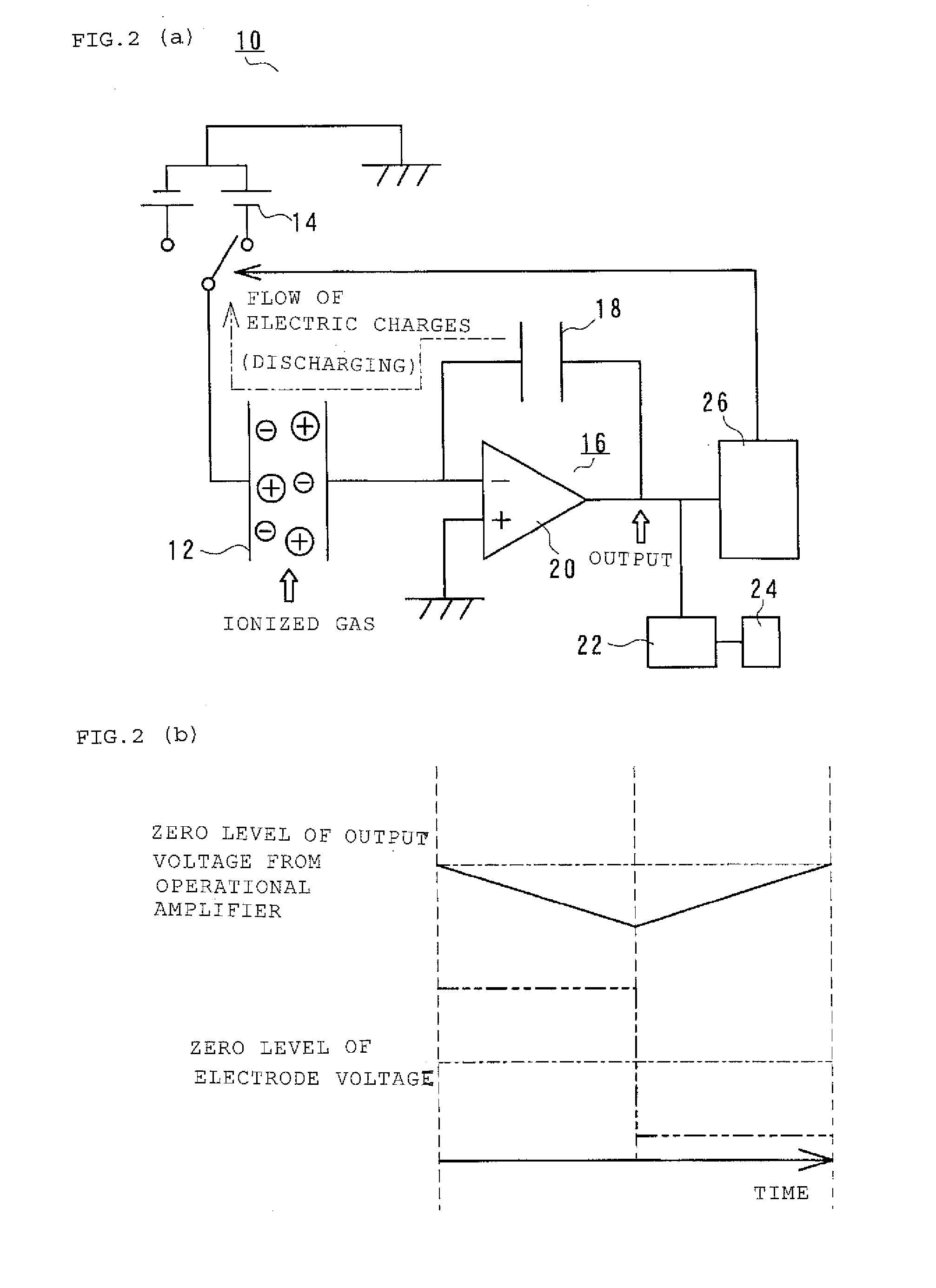
[0034]FIG. 1 depicts an example of a configuration of the ionized gas detector according to the first embodiment of the present invention, including FIG. 1A showing a diagram of an example of a circuit configuration of the detector and FIG. 1B showing the relation between a voltage between electrodes and an output voltage from a charge amplifier circuit. FIG. 2 depicts an example of the first embodiment of the ionized gas detector according to the present invention, including FIG. 2A showing a diagram of an example of a circuit configuration of the detector in which voltage polarity indicated in FIG. 1 is reversed and FIG. 2B showing the relation between a voltage between the electrodes and an output voltage from the charge amplifier circuit before and after the reversal of the voltage polarity. In FIG. 1, 10 denotes the ionized gas detector, 12 denotes the ion detec...
experiment 1
[0056](Experiment 1)
[0057]An ionized gas detection experiment has been conducted, using the ionized gas detector of the first embodiment of the present invention, under the following measurement conditions. A result of the experiment is shown in FIG. 3.
Ionized gas: toluene 10 ppm
Applied voltage: 20 V
Capacitance: 100 pF
[0058]Ion detecting electrodes: Electrodes insulated with a polyimide film
[0059]As shown in FIG. 3, the reversal of the voltage polarity causes an increase or decrease in an output voltage from the operational amplifier 20. This demonstrates a fact that even if insulated electrodes are used as the ion detecting electrodes, the ionized gas detector of this embodiment can detect an ionized gas with precision equal to the precision of detection of an ionized gas by the DC voltage applying method, thanks to transition phenomenon.
second embodiment
[0060]the ionized gas detector according to the present invention will then be described, referring to drawings.
[0061]FIG. 4 depicts an example of a configuration of the ionized gas detector of the second embodiment of the present invention, showing a diagram of an example of a circuit configuration of the detector. In FIG. 4, 28 denotes a voltage applying unit, 30 denotes a charge accumulating unit, 32 denotes a compensating circuit, and 34 denotes a voltage polarity reversing unit. Other components are denoted by the same reference numerals as used in FIGS. 1 and 2.
[0062]As shown in FIG. 4, the ionized gas detector 10 includes the ion detecting electrodes 12 that detect ions of an ionized measuring-subject gas flowing into the ionized gas detector 10, the electrode-voltage applying unit 14 that applies a voltage to the ion detecting electrodes 12 and that is configured to be capable of reversing its voltage polarity. The ionized gas detector 10 also includes the charge amplifier c...
PUM
 Abstract
Description
Claims
Application Information
 - R&D Engineer
- R&D Manager
- IP Professional
- Industry Leading Data Capabilities
- Powerful AI technology
- Patent DNA Extraction
Browse by: Latest US Patents, China's latest patents, Technical Efficacy Thesaurus, Application Domain, Technology Topic, Popular Technical Reports.
© 2024 PatSnap. All rights reserved.Legal|Privacy policy|Modern Slavery Act Transparency Statement|Sitemap|About US| Contact US: help@patsnap.com