Spiral surface electromagnetic wave dispersive delay line

Active Publication Date: 2014-09-18
AMI RES & DEV
View PDF2 Cites 9 Cited by
  • Summary
  • Abstract
  • Description
  • Claims
  • Application Information

AI Technical Summary

Benefits of technology

[0009]An electromagnetic dispersive delay line implemented in a spiral or practically spiral configuration provides wideband operation and high dispersion in a relatively compact form factor. In a preferred embodiment, the

Problems solved by technology

However, it is unclear whether a curved delay line could exh

Method used


Image

  • Spiral surface electromagnetic wave dispersive delay line
  • Spiral surface electromagnetic wave dispersive delay line
  • Spiral surface electromagnetic wave dispersive delay line

Examples


Embodiment Construction

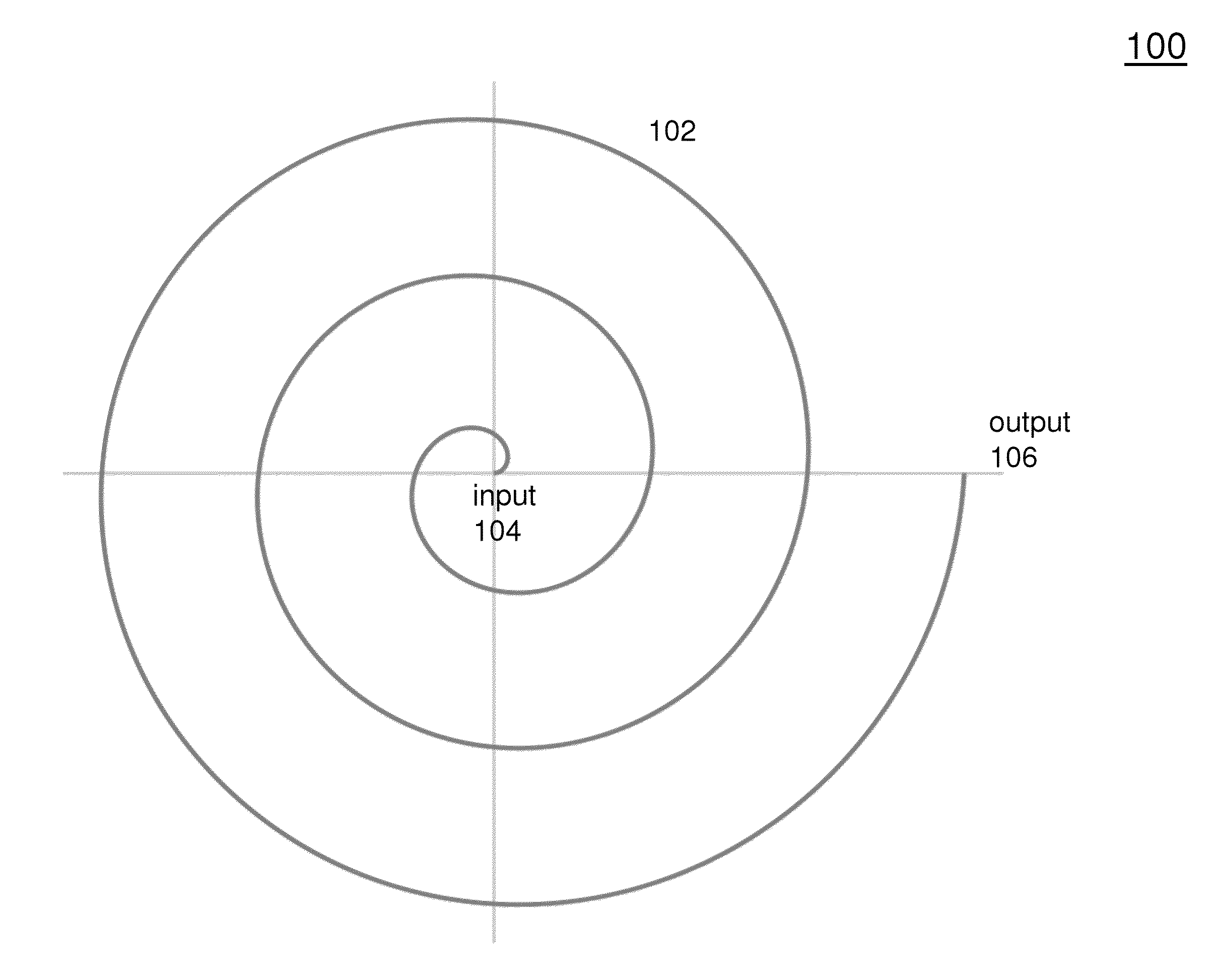
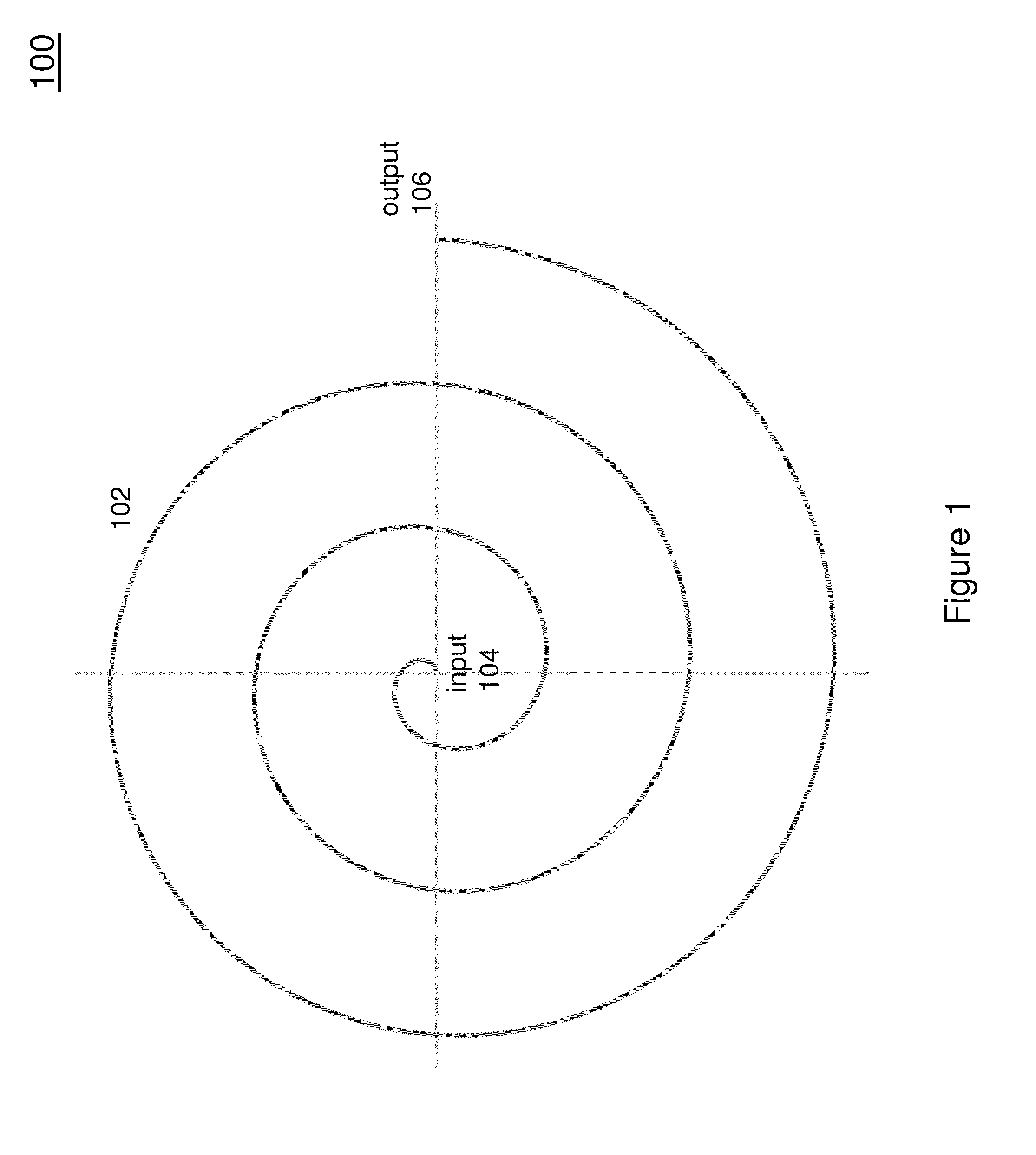
[0023]FIG. 1 is a plan view of a spiral electromagnetic dispersive delay line 100. In this arrangement, the spiral delay line 100 consists of a surface electromagnetic wave dispersive delay line 102. The delay line 102 is fed by an input transducer 104 and provides an output at a output transducer 106. In this arrangement, the spiral delay line 102 generally follows the geometry of an Archimedean spiral. However, it should be understood that other types of spirals could be implemented.

[0024]The radius of the spiral should be chosen so that the curvature of the spiral is compatible with a desired transmission mode. In particular, the radius of the spiral should not be so small as to prevent the waveguide from operating in its desired modes. It is known, for example, that in the case of a long straight waveguide, the electromagnetic wave will propagate approximately the same as in a coaxial cable. In case of a sinusoidal excitation, if the segment is considered to be one wavelength lo...


PUM


Abstract

Dispersive properties of a linear dispersive delay line are retained in a spiral configuration by constraining the radius of curvature depending on a desired propagation mode. The compact form factor spiral can be either a continuous spiral or a piecewise linear approximation. The spiral comprises a highly dielectric waveguide such as titanium dioxide or barium tetratitanate. Preferably, a spacer with a low dielectric constant and a microstrip are disposed on the top surface. The microstrip prevents attenuation of low frequencies, thereby increasing the operating frequency range. A second dielectric spacer and a second microstrip can be deposited on the bottom surface of the waveguide. Alternatively, the bottom surface of the waveguide can face a ground plane. The waveguide can be fed by horns or half-horns.

Description

RELATED APPLICATION[0001]This application claims the benefit of U.S. Provisional Application No. 61 / 781,543, filed Mar. 14, 2013, the contents of which are hereby incorporated herein by reference.BACKGROUND[0002]1. Technical Field[0003]This application relates to surface electromagnetic wave dispersive delay lines. It relates especially to high bandwidth dispersive delay lines formed in a compact spiral form factor.[0004]2. Background Information[0005]Dispersive delay lines have been used in defense technology for fifty years, first as matched filters for high power chirp radars, and then as an analog element in a Chirp Fourier Transform which is equivalent to an analog Fast Fourier Transform. By a simple factoring of the expression for the Fourier transform it can be shown that a temporal function or signal which is multiplied by a chirp waveform and fed into a dispersive delay line, matched to the multiplying chirp, produces a temporal waveform which is equivalent to the Fourier t...

Claims


Application Information

Patent Timeline
IPC IPC(8): H01P1/18H01P9/00
CPCH01P1/182H01P9/00H01P1/18
Inventor APOSTOLOS, JOHN T.MOUYOS, WILLIAMMCMAHON, BENJAMIN
Owner AMI RES & DEV
Why Eureka
Try Eureka