Selective laser solidification apparatus and method

a laser solidification and laser technology, applied in the direction of additive manufacturing processes, electric/magnetic/electromagnetic heating, manufacturing tools, etc., can solve problems such as non-uniform build conditions

Active Publication Date: 2014-09-18
RENISHAW PLC
View PDF4 Cites 60 Cited by
  • Summary
  • Abstract
  • Description
  • Claims
  • Application Information

AI Technical Summary

Benefits of technology

[0007]The order in which islands are formed may be selected such that debris produced by forming an island is carried away from areas of the powder layer in which islands are yet to be formed. In this way, these areas of powder are not disturbed and contaminated by the debris ensuring that, when these areas are solidified, the solidified layer is built to a desired, uniform height. For example, the processing unit may select to form at least part of an island before at least part of another island because the at least part of the island is located downwind in the gas flow direction of at least part of the other island. Debris produced in forming the upwind island may be blown onto the already formed downwind island but this debris will be covered by the next powder layer and the debris is likely to be remelted when forming the next cross-section. Accordingly, building the islands in this order is less likely to result in non-uniformities in the build.

Problems solved by technology

Accordingly, building the islands in this order is less likely to result in non-uniformities in the build.

Method used


Image

  • Selective laser solidification apparatus and method
  • Selective laser solidification apparatus and method
  • Selective laser solidification apparatus and method

Examples


Embodiment Construction

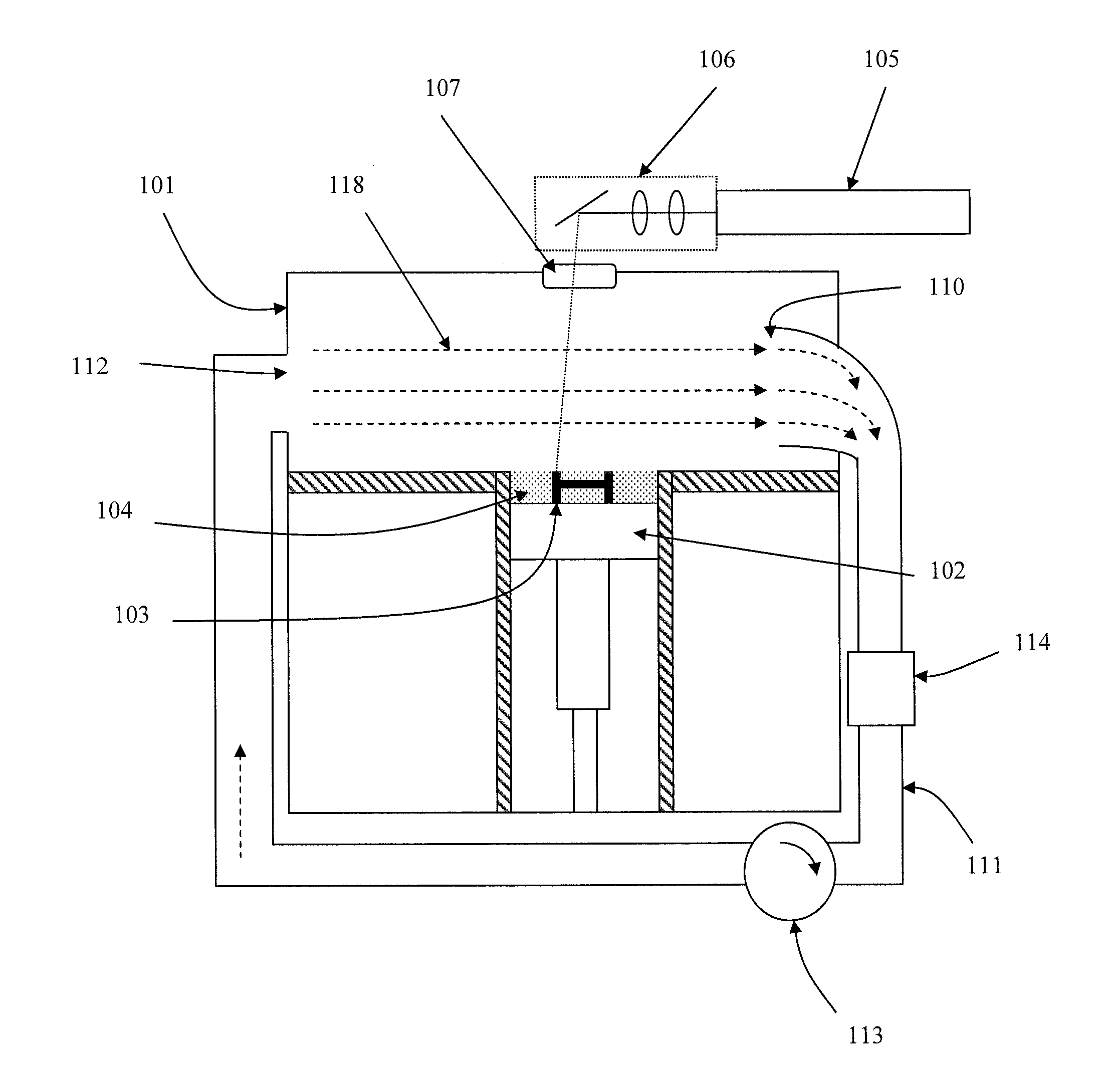
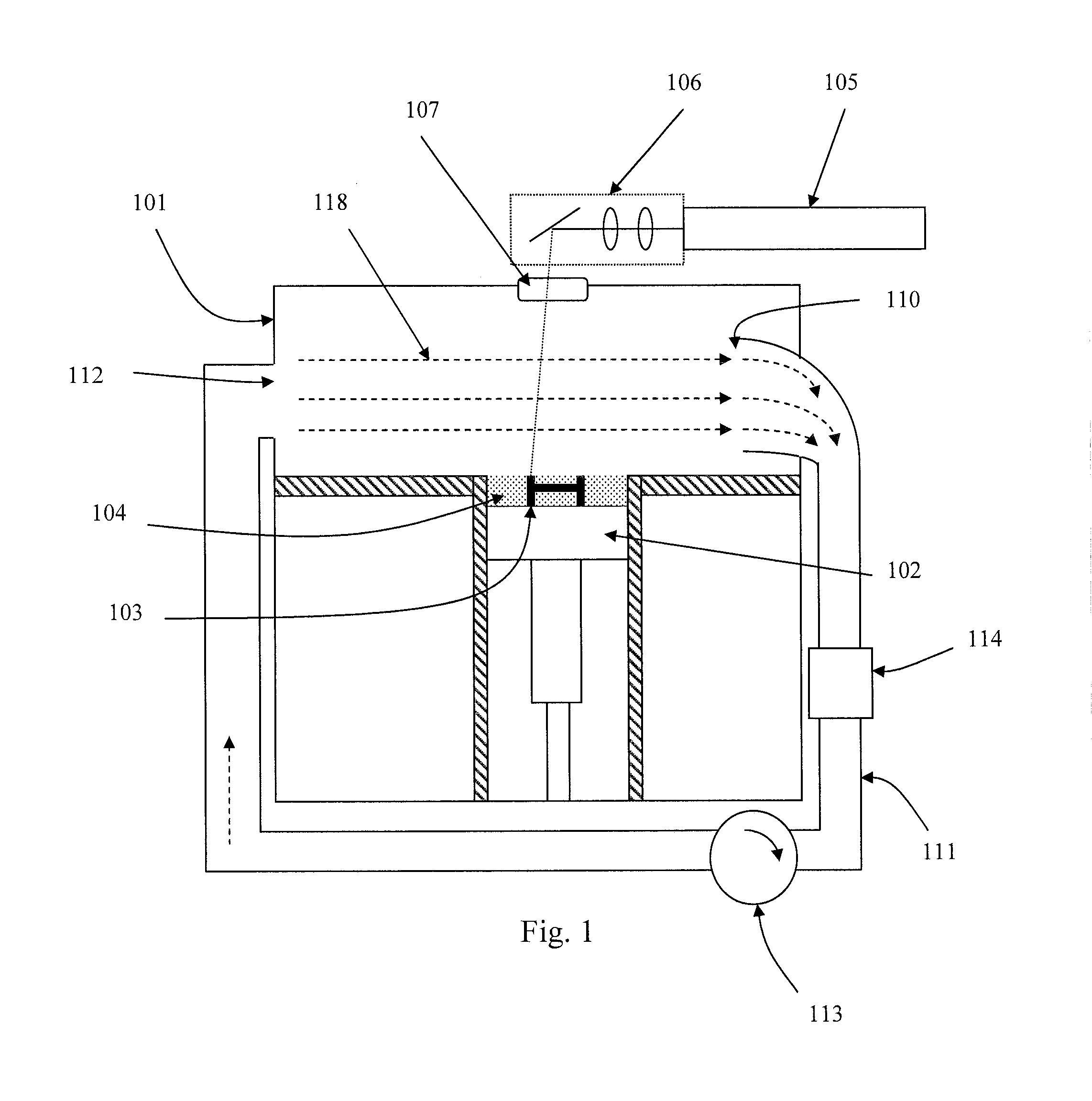
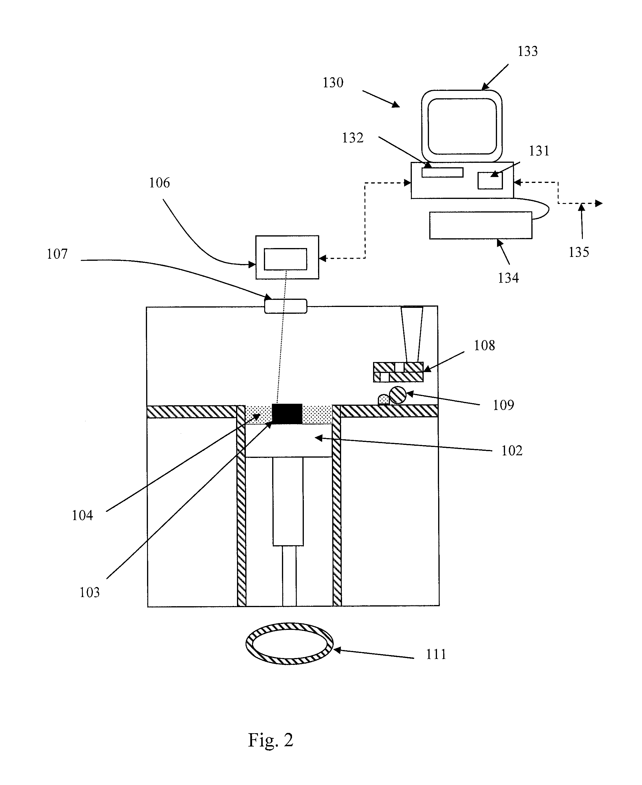
[0023]Referring to FIGS. 1 and 2, a laser solidification apparatus according to an embodiment of the invention comprises a build platform 102 for supporting an object 103 built by selective laser melting powder 104. The platform 102 can be lowered in the chamber 101 as successive layers of the object 103 are formed. Layers of powder 104 are formed as the object 103 is built by dispensing apparatus 108 and a wiper 109. For example, the dispensing apparatus 109 may be apparatus as described in WO2010 / 007396. A laser module 105 generates a laser for melting the powder 104, the laser directed as required by optical module 106 under the control of a computer 130. The laser enters the build chamber via a window 107.

[0024]An inlet 112 and outlet 110 are arranged for generating a gas flow across the powder bed formed on the build platform 102. The inlet 112 and outlet 110 are arranged to produce a laminar flow having a flow direction from the inlet to the outlet, as indicated by arrows 118....


PUM

PropertyMeasurementUnit
areaaaaaaaaaaa
thicknessaaaaaaaaaa
porosityaaaaaaaaaa

Abstract

A selective laser solidification apparatus including: a powder bed onto which a powder layer can be deposited, a gas flow unit for passing a flow of gas over the powder bed along a gas flow direction, a laser scanning unit for scanning a laser beam over the powder layer to selectively solidify at least part of the powder layer to form at least one object and a processing unit for selecting a scanning sequence of the laser beam based on the gas flow direction.

Description

[0001]The present invention relates to selective laser solidification and in particular to an improved selective laser melting process and apparatus in which an order in which objects or parts of objects are built is selected based on a direction of gas flow.BACKGROUND[0002]Additive manufacturing or rapid prototyping methods for producing objects comprise layer-by-layer solidification of a material, such as a metal powder material, using a laser beam. A powder layer is deposited on a powder bed in a build chamber and a laser beam is scanned across portions of the powder layer that correspond to a cross-section of the object being constructed. The laser beam melts or sinters the powder to form a solidified layer. After selective solidification of a layer, the powder bed is lowered by a thickness of the newly solidified layer and a further layer of powder is spread over the surface and solidified, as required. In a single build, more than one object can be built, the objects spaced ap...

Claims


Application Information

Patent Timeline
Patent Type & Authority Applications(United States)
IPC IPC(8): B29C67/00
CPCB29C67/0085B29C67/0077B33Y10/00B33Y30/00B29C64/153B29C64/386B29C64/268B29C64/364B29C64/182Y02P10/25B22F10/28B22F12/70B22F10/80B22F10/322B29C64/20B22F10/32B22F10/00B22F10/30B33Y50/02B23K26/342B22F3/101
Inventor FERRAR, BEN IAN
Owner RENISHAW PLC
Why Eureka
Try Eureka