Coating Process of Zero-PGM Catalysts and Methods Thereof
- Summary
- Abstract
- Description
- Claims
- Application Information
AI Technical Summary
Benefits of technology
Problems solved by technology
Method used
Image

Examples
example # 1
Example #1
Coating Process Type 1, Co-Precipitation of Cu—Mn Spinel / Nb2O5—ZrO2 Support Oxide
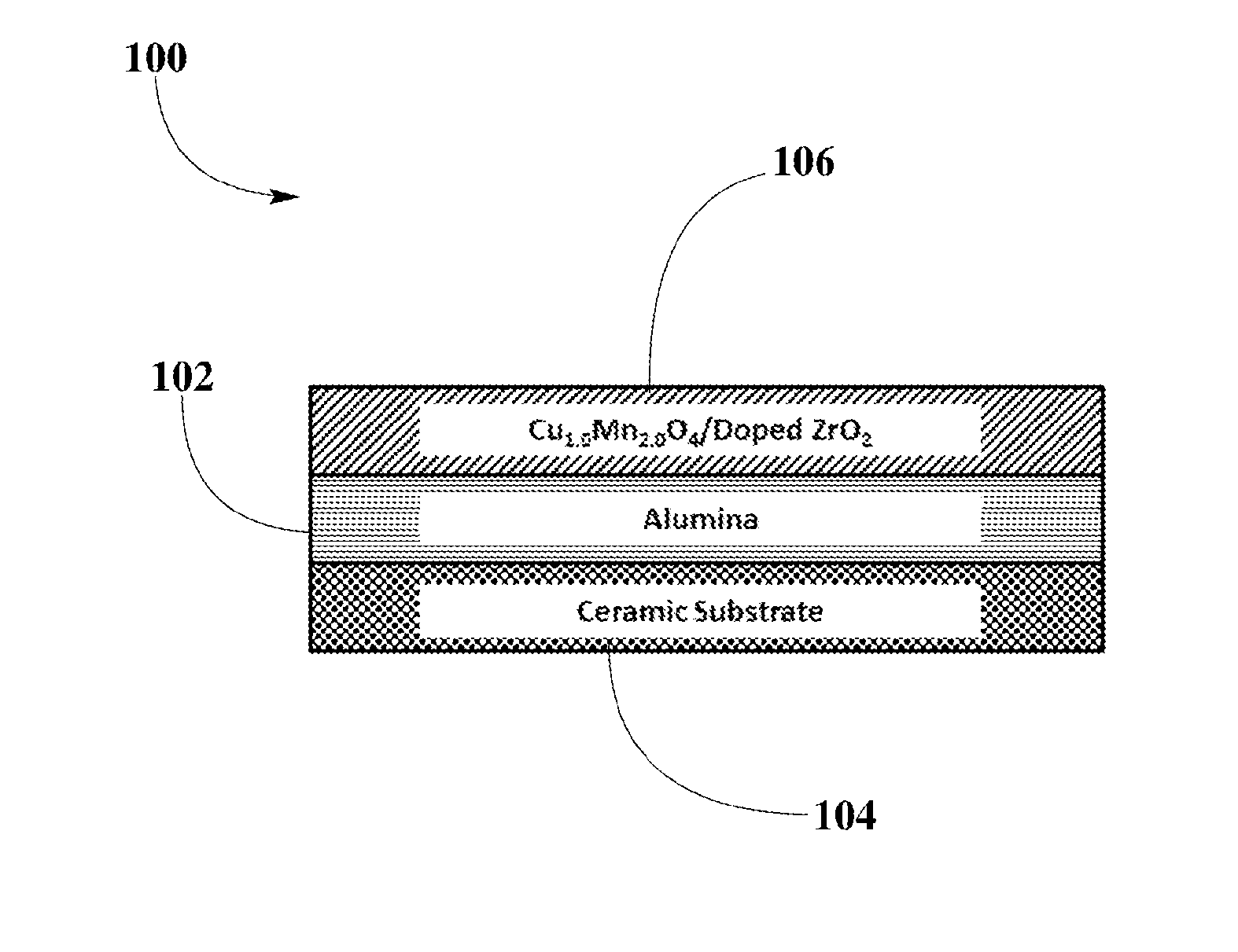
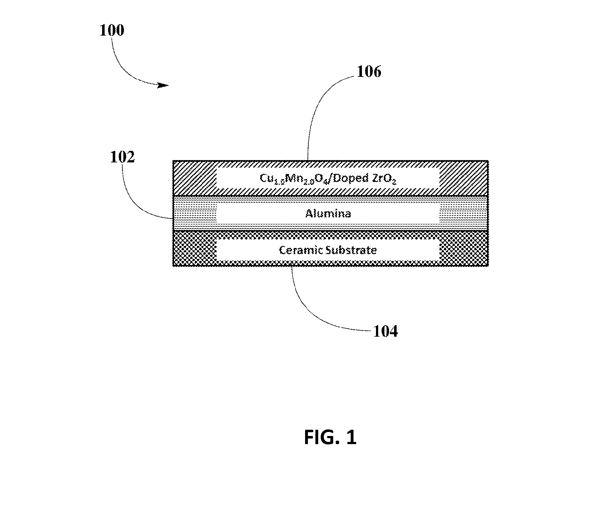
[0057]Example #1 may illustrate preparation of ZPGM catalyst samples of catalyst configuration 100 employing coating process here referred as coating process Type 1. Co-precipitation method may be employed in this process. Preparation of WC layer 102 may start by milling alumina solution to make slurry. Suitable loading of alumina may be about 120 g / L. Alumina slurry may be subsequently coated on ceramic substrate 104 and fired (calcined) at about 550° C. for about 4 hours. Preparation of OC layer 106 may start by milling Nb2O5—ZrO2 support oxide with water separately to make slurry. Then, Cu—Mn solution may be prepared by mixing the appropriate amount of Mn nitrate solution (Mn(NO3)2) and Cu nitrate solution (CuNO3) with water to make solution at appropriate molar ratio for Cu1.0Mn2.0O4, according to formulation CuXMn3-XO4, in which X may take value of 1.0. Subsequently, Cu—Mn solution may be...
example # 2
Example #2
Coating Process Type 2, Cu—Mn Spinel Bulk Powder / Nb2O5—ZrO2 Support Oxide
[0062]Example #2 may illustrate preparation of ZPGM catalyst samples of catalyst configuration 100 employing coating process here referred as coating process Type 2. Preparation of WC layer 102 may start by milling alumina solution to make slurry. Suitable loading of alumina may be about 120 g / L. Alumina slurry may be subsequently coated on ceramic substrate 104 and fired at about 550° C. for about 4 hours. Preparation of OC layer 106 may start by milling Nb2O5—ZrO2 support oxide with water separately to make slurry. Then, Cu—Mn solution may be prepared by mixing the appropriate amount of Mn nitrate solution (Mn(NO3)2) and Cu nitrate solution (CuNO3) with water to make solution at appropriate molar ratio for Cu1.0Mn2.0O4, according to formulation CuXMn3-XO4, in which X may take value of 1.0. Subsequently, Cu—Mn solution may be precipitated using an appropriate amount of base solution to adjust pH of s...
example # 3
Example #3
Coating Process Type 3, Cu—Mn Spinel / Nb2O5—ZrO2 Bulk Powder
[0068]Example #3 may illustrate preparation of ZPGM catalyst samples of catalyst configuration 100 employing coating process here referred as coating process Type 3. Preparation of WC layer 102 may start by milling alumina solution to make slurry. Suitable loading of alumina may be about 120 g / L. Alumina slurry may be subsequently coated on ceramic substrate 104 and calcined (fired) at about 550° C. for about 4 hours. Preparation of OC layer 106 may start by milling Nb2O5—ZrO2 support oxide with water separately to make slurry. Then, Cu—Mn solution may be prepared by mixing the appropriate amount of Mn nitrate solution (Mn(NO3)2) and Cu nitrate solution (CuNO3) with water to make solution at appropriate molar ratio for Cu1.0Mn2.0O4, according to formulation CuXMn3-XO4, in which X may take value of 1.0. Then, Cu—Mn solution may be mixed with slurry of Nb2O5—ZrO2 support oxide for about 2 hours to 4 hours. Subsequent...
PUM
| Property | Measurement | Unit |
|---|---|---|
| Time | aaaaa | aaaaa |
Abstract
Description
Claims
Application Information
 - Generate Ideas
- Intellectual Property
- Life Sciences
- Materials
- Tech Scout
- Unparalleled Data Quality
- Higher Quality Content
- 60% Fewer Hallucinations
Browse by: Latest US Patents, China's latest patents, Technical Efficacy Thesaurus, Application Domain, Technology Topic, Popular Technical Reports.
© 2025 PatSnap. All rights reserved.Legal|Privacy policy|Modern Slavery Act Transparency Statement|Sitemap|About US| Contact US: help@patsnap.com