Infrared Detection Element, Infrared Detection Module, and Manufacturing Method Therefor

Active Publication Date: 2014-09-25
NGK INSULATORS LTD
View PDF5 Cites 2 Cited by
  • Summary
  • Abstract
  • Description
  • Claims
  • Application Information

AI Technical Summary

Benefits of technology

The present invention relates to an infrared detection element and an infrared detection module with improved sensitivity and high-speed response. The invention addresses the issue of deformation of the pyroelectric substrate, which can cause piezoelectric noise and reduce the S / N ratio, by reducing the thickness of the substrate. The invention achieves this by using a Y-offcut plate of lithium tantalate with a cut angle of 10-30 degrees, which reduces deformation of the substrate. Additionally, the invention suppresses deformation of the substrate by using a second substrate with a lower thermal expansion coefficient than the pyroelectric substrate. The invention also includes a conductive adhesive material that bonds the infrared detection element and the second substrate, further reducing deformation of the substrate. The thermal expansion coefficient difference between the first and second substrates is 8.9 ppm / K or less, further suppressing deformation of the pyroelectric substrate. The invention also provides various methods for manufacturing the infrared detection element and module.

Problems solved by technology

Then, the change in temperature changes spontaneous polarization, disturbs the balance of electric charge on the surface of the pyroelectric substrate, and causes generation of electric charge.

Method used

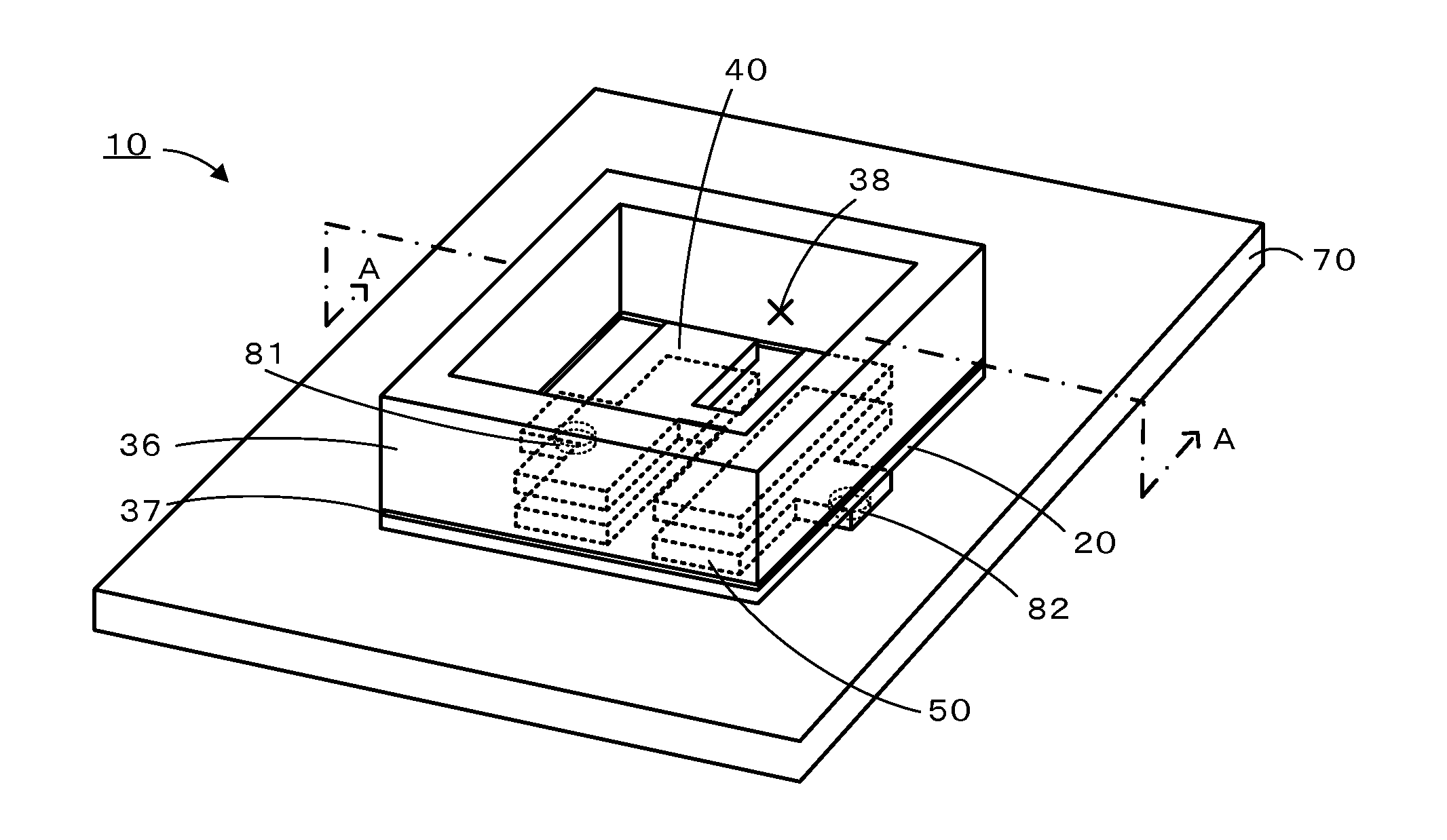
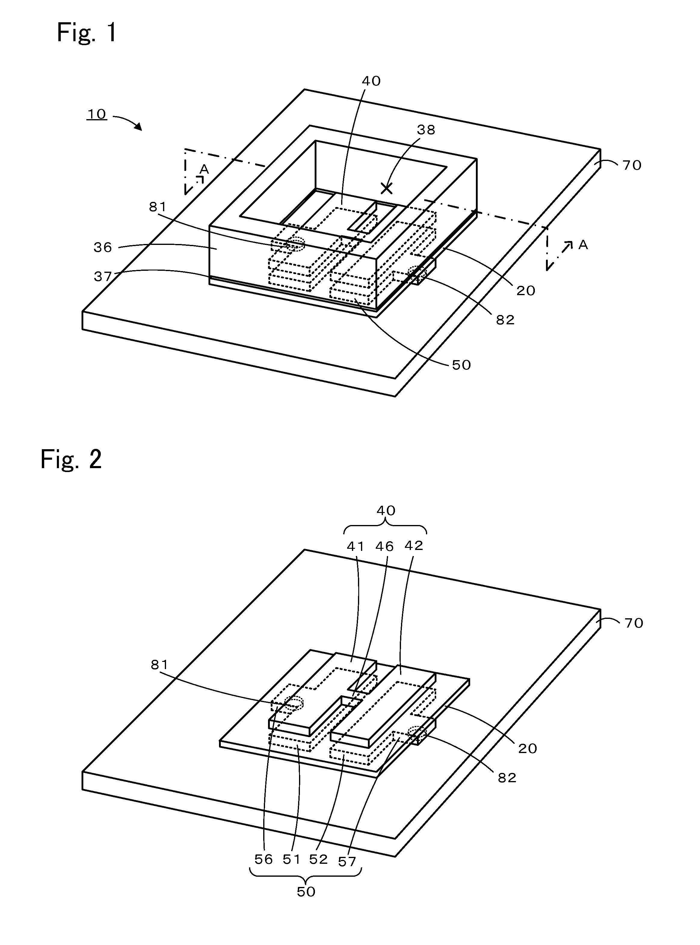
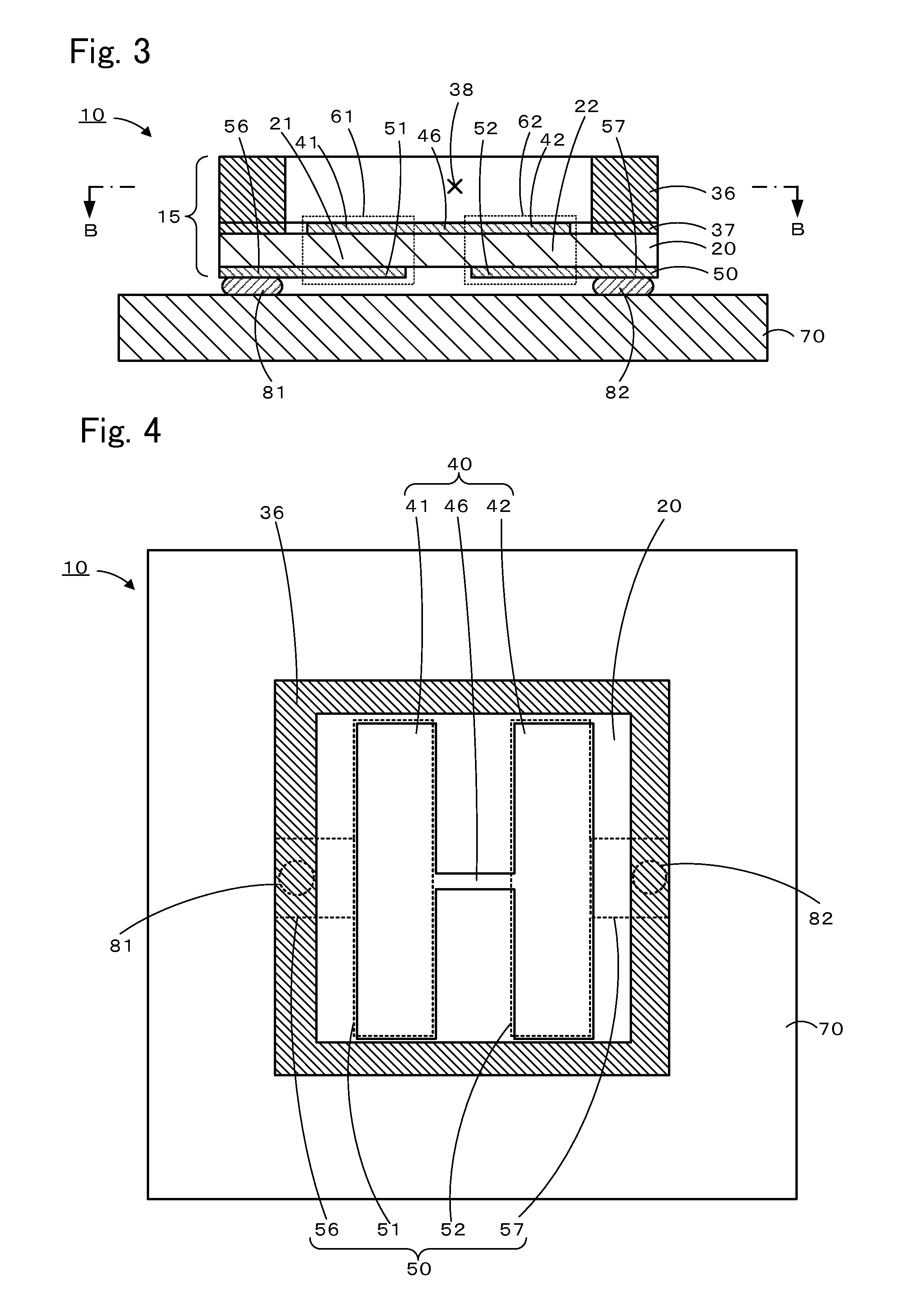

Image

  • Infrared Detection Element, Infrared Detection Module, and Manufacturing Method Therefor
  • Infrared Detection Element, Infrared Detection Module, and Manufacturing Method Therefor
  • Infrared Detection Element, Infrared Detection Module, and Manufacturing Method Therefor

Examples


experimental example 1

[0076]As Experimental Example 1, the infrared detection module 10 of the embodiment was manufactured by the above-described method.

[0077]First, a pyroelectric substrate 120 formed by an LT substrate including an OF portion and having a diameter of 4 inches and a thickness of 350 μm (having a thermal expansion coefficient of 17 ppm / K) was prepared (FIG. 7(a)). As the pyroelectric substrate 120, a 48° Y-offcut plate (cut angle) θ=48° was used. The pyroelectric substrate 120 is to be divided into pyroelectric substrates 20 by dicing. Subsequently, multiple front-side metal layers 140 made of nickel and chromium were formed on a front side of the pyroelectric substrate 120 (FIG. 7(b), FIG. 8(a)). The front-side metal layers 140 were formed by vacuum evaporation using a metal mask that covered the pyroelectric substrate 120 except for areas where the front-side metal layers 140 were to be formed. Vacuum evaporation was performed by first depositing a chromium film at a deposition rate of...

experimental examples 2 to 10

[0084]Infrared detection modules 10 of Experimental Examples 2 to 10 were manufactured in a manner similar to that adopted in Experimental Example 1 except that the thermal expansion coefficient of a glass substrate to become a first substrate 36 was different from that adopted in Experimental Example 1.

experimental example 11

[0085]An infrared detection module 10 of Experimental Example 11 was manufactured in a manner similar to that adopted in Experimental Example 1 except that a circuit board having electric wiring on an alumina substrate (thermal expansion coefficient: 7 ppm / K) was used as a second substrate 70.


PUM

PropertyMeasurementUnit
Thicknessaaaaaaaaaa
Angleaaaaaaaaaa
Temperature coefficient of resistanceaaaaaaaaaa

Abstract

In an infrared detection element 15, a first substrate 36 is bonded to a front side of a pyroelectric substrate 20. Since the thermal expansion coefficient of the first substrate 36 is lower than that of the pyroelectric substrate 20, deformation of the pyroelectric substrate 20 due to thermal expansion can be suppressed by the first substrate 36. Further, since a thermal expansion coefficient difference D is 8.9 ppm / K or less, the thermal expansion coefficient between the first substrate 36 and the pyroelectric substrate 20 is not excessively large, and this can suppress deformation of the infrared detection element 15 due to the thermal expansion coefficient difference between the first substrate 36 and the pyroelectric substrate 20.

Description

BACKGROUND OF THE INVENTION[0001]1. Field of the Invention[0002]The present invention relates to an infrared detection element, an infrared detection module, and a manufacturing method therefor.[0003]2. Description of the Related Art[0004]Pyroelectric elements have been used as infrared detection elements in infrared detection modules for security and gas detection purposes. A pyroelectric element includes a pyroelectric substrate and a pair of front-side and back-side electrodes provided on front and back sides of the pyroelectric substrate, respectively. When a surface of the pyroelectric element is irradiated with infrared light, the temperature of the pyroelectric substrate increases. Then, the change in temperature changes spontaneous polarization, disturbs the balance of electric charge on the surface of the pyroelectric substrate, and causes generation of electric charge. By extracting the generated electric charge through conductive wires connected to the pair of electrodes,...

Claims


Application Information

Patent Timeline
IPC IPC(8): G01J5/04
CPCG01J5/046G01J5/34Y10T156/10H10N15/10
Inventor KONDO, JUNGOSUZUKI, KENJI
Owner NGK INSULATORS LTD
Why Eureka
Try Eureka