
Multi-functional catheter

Inactive Publication Date: 2014-09-25
PHANGENESIS LTD
View PDF8 Cites 13 Cited by
  • Summary
  • Abstract
  • Description
  • Claims
  • Application Information

AI Technical Summary

Benefits of technology

The present invention relates to a pharyngeal stimulation catheter that can deliver nutrition and electrical stimulation to a patient's oropharynx. However, the accurate positioning of the catheter can be challenging. To address this problem, the catheter incorporates a position indicator and a sensor that provides diagnostic information to facilitate accurate placement of the electrodes. This improves the efficacy and safety of the catheter.

Problems solved by technology

The present inventors have, however, found that accurate positioning of the catheter disclosed in Hamdy can be problematic.
This introduces risks that the distal end of the catheter does not remain in the stomach but continues into the duodenum, becomes entangled in the stomach preventing effective nutrition delivery or easy removal, or re-emerges from the stomach into the lower oesophagus.
The fixed positioning of both electrical stimulation and nutrition functions in the invention of Hamdy et al. also has the disadvantage that, in the event the internal lumen of the catheter becomes blocked with nutritional feed in a way that cannot be resolved, the entire catheter must be replaced.
This is not desirable from a patient comfort or safety management perspective.

Method used


Image

  • Multi-functional catheter
  • Multi-functional catheter
  • Multi-functional catheter

Examples


first embodiment

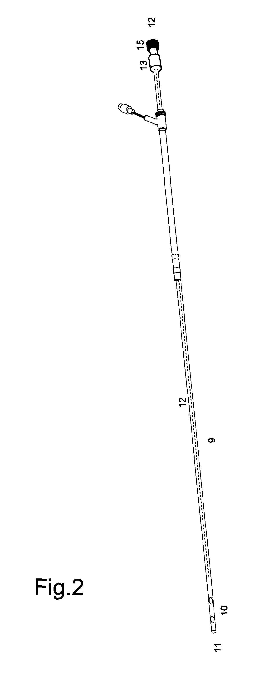
[0102]In the first embodiment shown in FIG. 2 a catheter is described which has the dual functions of therapeutic electrical stimulation to treat acute dysphagia and delivery of enteral nutrition.

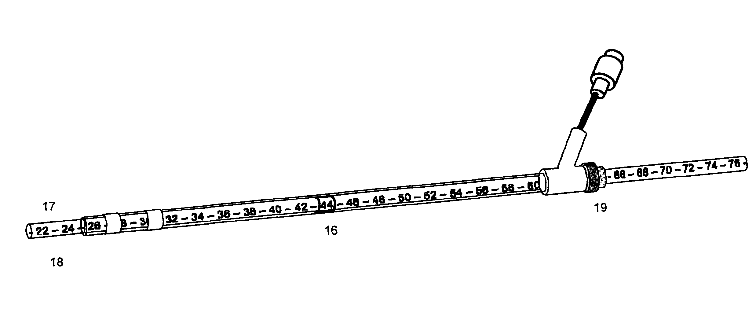
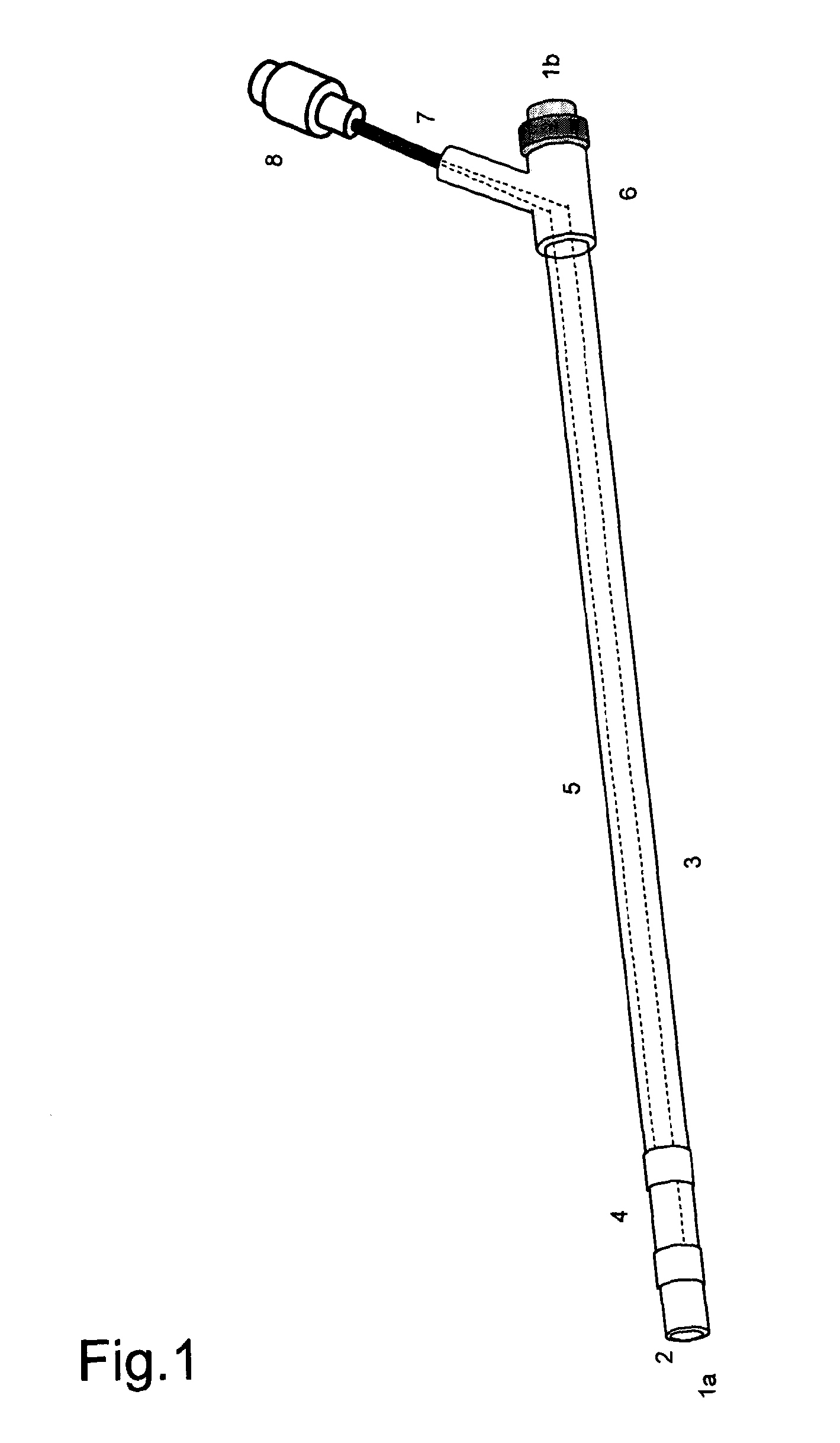
[0103]It comprises a core elongate structure in the form of a custom nasogastric (NG) feeding tube (9) onto which is disposed a sleeve capable of freely moving along the length of the NG tube. The sleeve is a substantially transparent flexible tube made of polyurethane, PVC, polyamide, silicone or equivalent material, typically 4.7 mm in outer diameter, with an internal lumen 3.3 mm diameter and 35-45 cm in length, incorporating a pair of ring electrodes, conducting elements disposed laterally along the walls of the tube connected to the electrodes and a Y-connector to guide the wires to an electrical connector. The internal surface of the sleeve may be modified with respect to its hardness, shape, finish or coating such that the modification helps to minimise friction when the sleeve is pl...

second embodiment

[0115]In a second embodiment shown in FIGS. 4a and 4b the device has the dual functions of electrical pharyngeal stimulation and measurement. It comprises a core elongate structure (9) onto which is disposed a sleeve capable of freely moving along the length of the catheter. The sleeve is a substantially transparent flexible tube made of polyurethane, PVC, polyamide, silicone or equivalent material, typically 4.7 mm in outer diameter, with an internal lumen 3.3 mm diameter and 35-45 cm in length, incorporating a pair of ring electrodes, conducting elements disposed laterally along the walls of the tube connected to the electrodes and a Y-connector to guide the wires to an electrical connector. The internal surface of the sleeve may be modified with respect to its hardness, shape, finish or coating such that the modification helps to minimise friction when the sleeve is placed or moved along the catheter on which it is positioned. The sleeve has a printed guide or window on its surfa...


PUM


Abstract

A catheter suitable for delivering an electric current to the body, in particular a catheter having electrodes that can be positioned independently of the main elongate shaft of the catheter. More particularly the catheters include a movable sleeve that incorporates the electrodes. A movable sleeve includes one or more electrodes and advances in the construction of the electrodes and related components is disclosed. Methods for positioning electrodes at a treatment site in the body for diagnostic or therapeutic applications, particularly electrical pharyngeal stimulation are also disclosed.

Description

[0001]The present invention relates to novel catheters suitable for delivering an electric current to the body, in particular to catheters that have electrodes that can be positioned independently of the main elongate shaft of the catheter. More particularly the invention relates to catheters that include a movable sleeve that incorporates the electrodes. It also relates to a movable sleeve that includes one or more electrodes and to advances in the construction of the electrodes and related components. The invention also relates to methods for positioning electrodes at a treatment site in the body for diagnostic or therapeutic applications.[0002]Catheters that include electrodes that are used for diagnosis, measuring and other medical applications are well known, catheters comprising multiple electrodes, for example, see U.S. Pat. No. 5,109,870 Silny. Whilst catheters comprising electrodes are known in the art, they suffer from a number of disadvantages.[0003]International patent p...

Claims


Application Information

Patent Timeline
IPC IPC(8): A61B5/0492A61N1/05A61J15/00A61B5/08A61B5/296
CPCA61B5/0492A61B5/08A61J2015/0084A61J15/0026A61N1/05A61N1/0517A61B5/037A61B5/14539A61M2025/0002A61M2025/0004A61M2025/0006A61M2025/0008A61J15/0084A61B5/6852A61B5/392A61B18/1492A61M25/00A61B5/296
Inventor MULROONEY, CONOR
Owner PHANGENESIS LTD
Learn More