
Focused ion beam apparatus and control method thereof

a focused ion beam and apparatus technology, applied in the direction of electrical apparatus, cathode ray tube/electron beam tube, electric discharge tube, etc., can solve the problems of difficult machining in a case where an appropriate, damage to a sample becomes serious, and the effect of a short time for the exchange of ions

Active Publication Date: 2014-10-02
HITACHI HIGH TECH SCI CORP
View PDF16 Cites 7 Cited by
  • Summary
  • Abstract
  • Description
  • Claims
  • Application Information

AI Technical Summary

Benefits of technology

The invention is about a focused ion beam apparatus that can quickly change the type of ion in its source without leaving any gas behind. This makes it possible to quickly switch between different types of ions in a short period of time. The control method for this apparatus is also provided. This technology helps to improve the efficiency and flexibility of focused ion beam apparatuses, which can be used in a variety of fields such as materials science and biological research.

Problems solved by technology

In the machining technique using the gallium ion beam, any materials can be etched by a sputtering effect, but damage to a sample from gallium injection is serious.
On the other hand, in the case of the machining technique using the electron beam or the helium ion beam, damage to a sample is slight, but since it is necessary to use a gas having an etching promotion function, it is difficult to perform machining in a case where an appropriate gas is not present.
Thus, when it is necessary to perform machining using ion species having a small mass, ion species having a large mass may be mixed, and in this case, damage to a sample becomes serious.
In the latter method (i.e., extracting only a desired ion species), a beam of a single ion species are obtained, but an ion optical system is complicated and enlarged, and a beam diameter may not be narrowed down.
That is, according to the both above-mentioned methods, since it is difficult to prevent performance deterioration, the method of exchanging the source gas to be supplied to the ion source chamber is considered again.
Thus, in this method, it is necessary to wait until the purity of the gas after exchange increases, which causes a problem that an ion species exchange time becomes long.

Method used


Image

  • Focused ion beam apparatus and control method thereof
  • Focused ion beam apparatus and control method thereof
  • Focused ion beam apparatus and control method thereof

Examples


Embodiment Construction

[0027]Hereinafter, illustrative embodiments of the invention will be described with reference to the accompanying drawings.

First Illustrative Embodiment

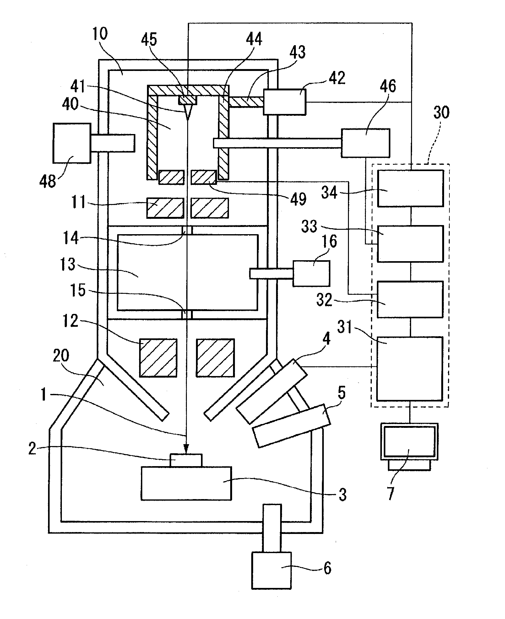
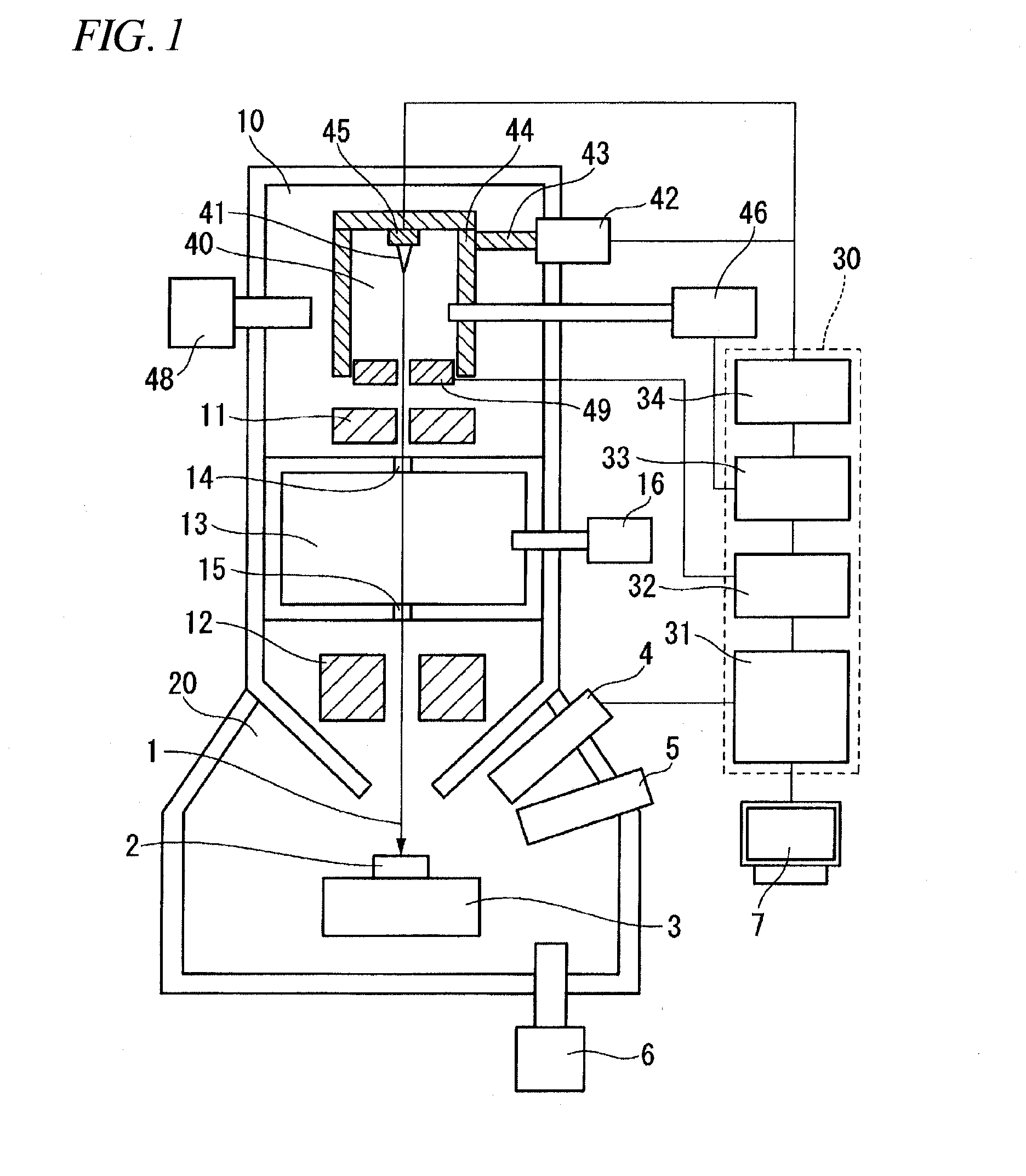
[0028]FIG. 1 shows a focused ion beam apparatus provided with a gas electric field ionization ion source according to an illustrative embodiment of the invention. The gas electric field ionization ion source forms a high electric field around a tip of an emitter 41 sharpened at an atomic level in an ion source chamber 40 in which an ion source gas is supplied to ionize the ion source gas adsorbed to the tip, and emits an ion beam 1. Since the ion beam 1 emitted from the tip of the emitter 41 has a fine light source diameter of several angstroms, it is possible to irradiate a sample 2 with the ion beam 1 having a small beam diameter and a high luminance.

[0029]In order to machine the sample 2 by the ion beam 1, the focused ion beam apparatus emits the ion beam 1, using nitrogen with a high sputtering effect, instead of a light element ...


PUM


Abstract

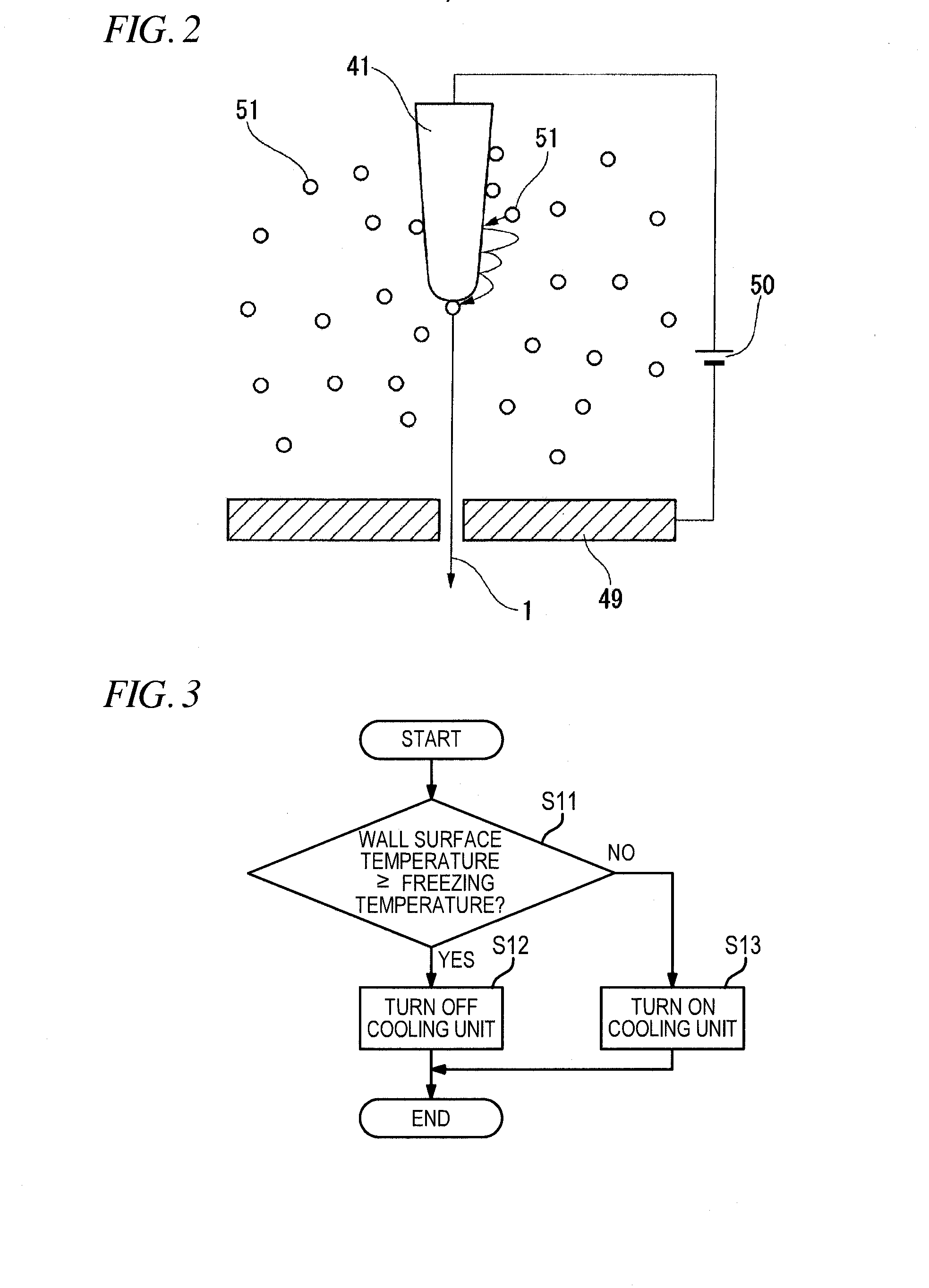
A focused ion beam apparatus is configured to perform at least one of a process of controlling an operation of a cooling unit so that a temperature of a wall surface contacting a source gas in an ion source chamber is maintained at a temperature higher than a temperature at which the source gas freezes and a process of controlling an operation of a heater so that an emitter is temporarily heated when the source gas is exchanged.

Description

[0001]This application claims priority from Japanese Patent Application No. 2013-066221 filed on Mar. 27, 2013, the entire subject-matter of which is incorporated herein by reference.BACKGROUND[0002]1. Technical Field[0003]The disclosure relates to a focused ion beam apparatus provided with a gas electric field ionization ion source (GFIS) and a control method thereof.[0004]2. Description of Related Art[0005]In the related art, as a device that observes an image at high resolution, a scanning electron microscope (SEM) using an electron beam is widely known. Further, in recent years, a scanning electron microscope using helium ions emitted from a gas electric field ionization ion source (GFIS) has also been in practical use.[0006]As a device that machines a random position, a machining device using gallium ions emitted from a liquid metal ion source (LIMS) is widely known. This device is used for cross-section observation of an arbitrary location of a sample, manufacturing of a TEM s...

Claims


Application Information

Patent Timeline
IPC IPC(8): H01J37/30
CPCH01J37/3007H01J37/08H01J2237/002H01J2237/0807
Inventor ARAMAKI, FUMIOSUGIYAMA, YASUHIKOOBA, HIROSHI
Owner HITACHI HIGH TECH SCI CORP
Learn More