

Honeycomb structure and manufacturing method of the same
a honeycomb structure and manufacturing method technology, applied in the field of honeycomb structure, can solve the problems of not easily flowing, heat is not sufficiently generated in a portion through which the current cannot easily flow, and the portion which is not easily heated is created in the honeycomb structure body, so as to reduce the uneven heat generation and reduce the electric resistance of the electrode section
- Summary
- Abstract
- Description
- Claims
- Application Information
AI Technical Summary
Benefits of technology
Problems solved by technology
Method used
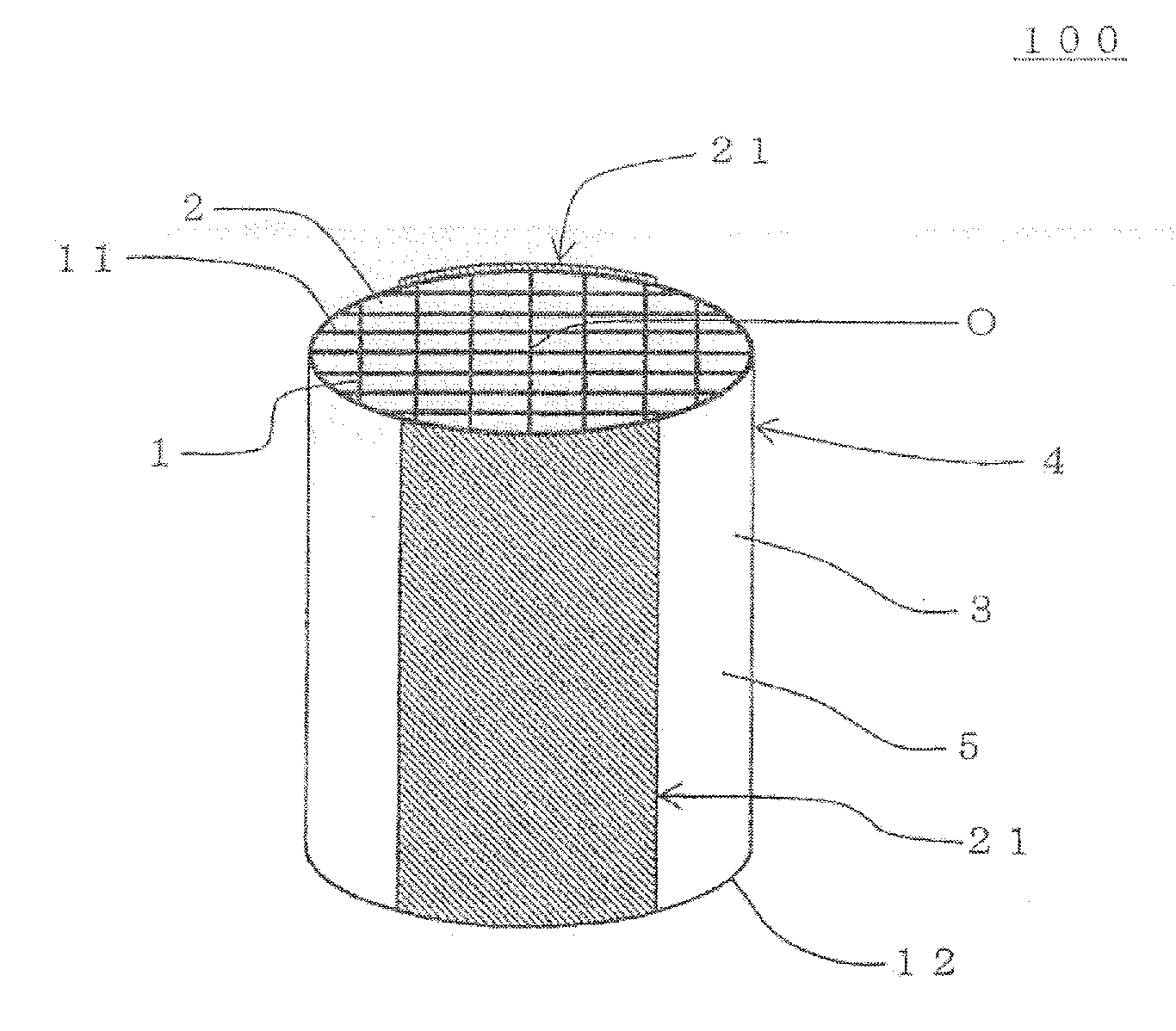
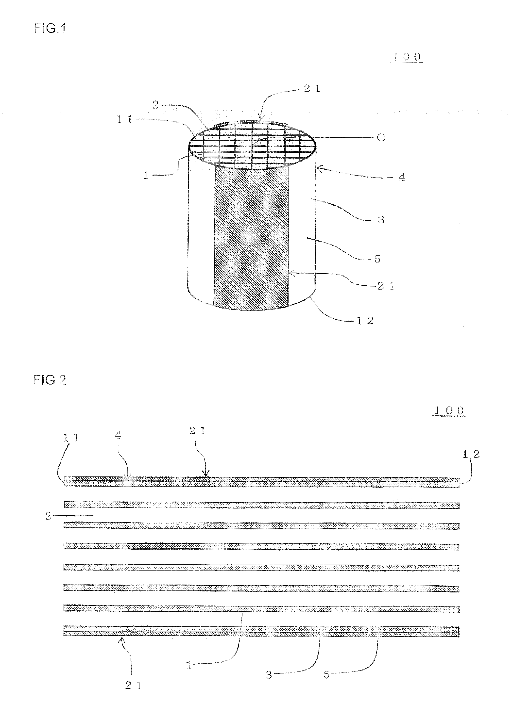
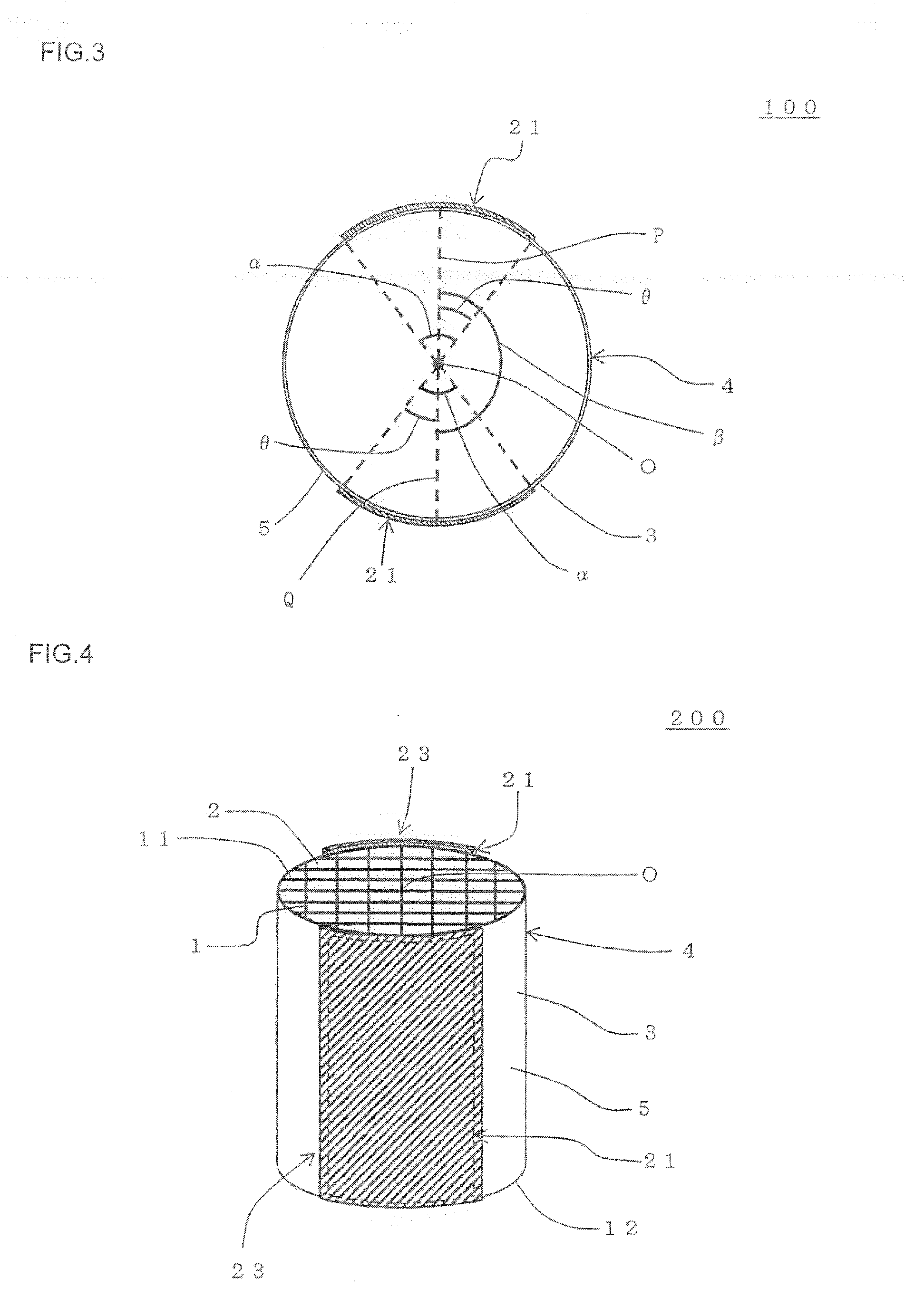
Image

Examples
example 1
[0124]Silicon powder, silicon carbide powder, cordierite powder as oxide particles, methylcellulose, glycerin, a polyacrylic dispersant and water were mixed by a rotation and revolution type stirrer, to prepare an electrode section forming raw material.
[0125]As the silicon powder, 52 g of silicon powder having an average particle diameter of 5 μm and a density of 2.33 g / cm3 was used. As the silicon carbide powder, 48 g of silicon carbide powder having an average particle diameter of 3 μm and a density of 3.17 g / cm3 was used. As the cordierite powder, 5.0 g of cordierite powder having an average particle diameter of 2 μm and a density of 2.65 g / cm3 was used. Furthermore, an amount of methylcellulose to be used was 0.8 g, an amount of glycerin to be used was 9 g, and an amount of the polyacrylic dispersant to be used was 0.1 g. Furthermore, an amount of the water as a dispersion medium to be used was 40 g.
[0126]Furthermore, a honeycomb forming raw material for preparing a honeycomb st...
example 2
[0130]The procedures of Example 1 were repeated except that as an electrode section forming raw material, 58 g of silicon powder of 5 μm, 42 g of silicon carbide powder of 3 μm and 5.0 g of cordierite powder of 2 μm were used, to prepare a honeycomb structure. Densities of the silicon powder, the silicon carbide powder and the cordierite powder were the same values as in Example 1.
example 3
[0131]The procedures of Example 1 were repeated except that as an electrode section forming raw material, 58 g of silicon powder of 2 μm, 42 g of silicon carbide powder of 3 μm and 5.0 g of cordierite powder of 2 μm were used, to prepare a honeycomb structure. Densities of the silicon powder, the silicon carbide powder and the cordierite powder were the same values as in Example 1.
PUM
| Property | Measurement | Unit |
|---|---|---|
| Thickness | aaaaa | aaaaa |
| Thickness | aaaaa | aaaaa |
| Percent by volume | aaaaa | aaaaa |
Abstract
Description
Claims
Application Information