
Honeycomb structure

Active Publication Date: 2014-10-02
NGK INSULATORS LTD
View PDF16 Cites 5 Cited by
  • Summary
  • Abstract
  • Description
  • Claims
  • Application Information

AI Technical Summary

Benefits of technology

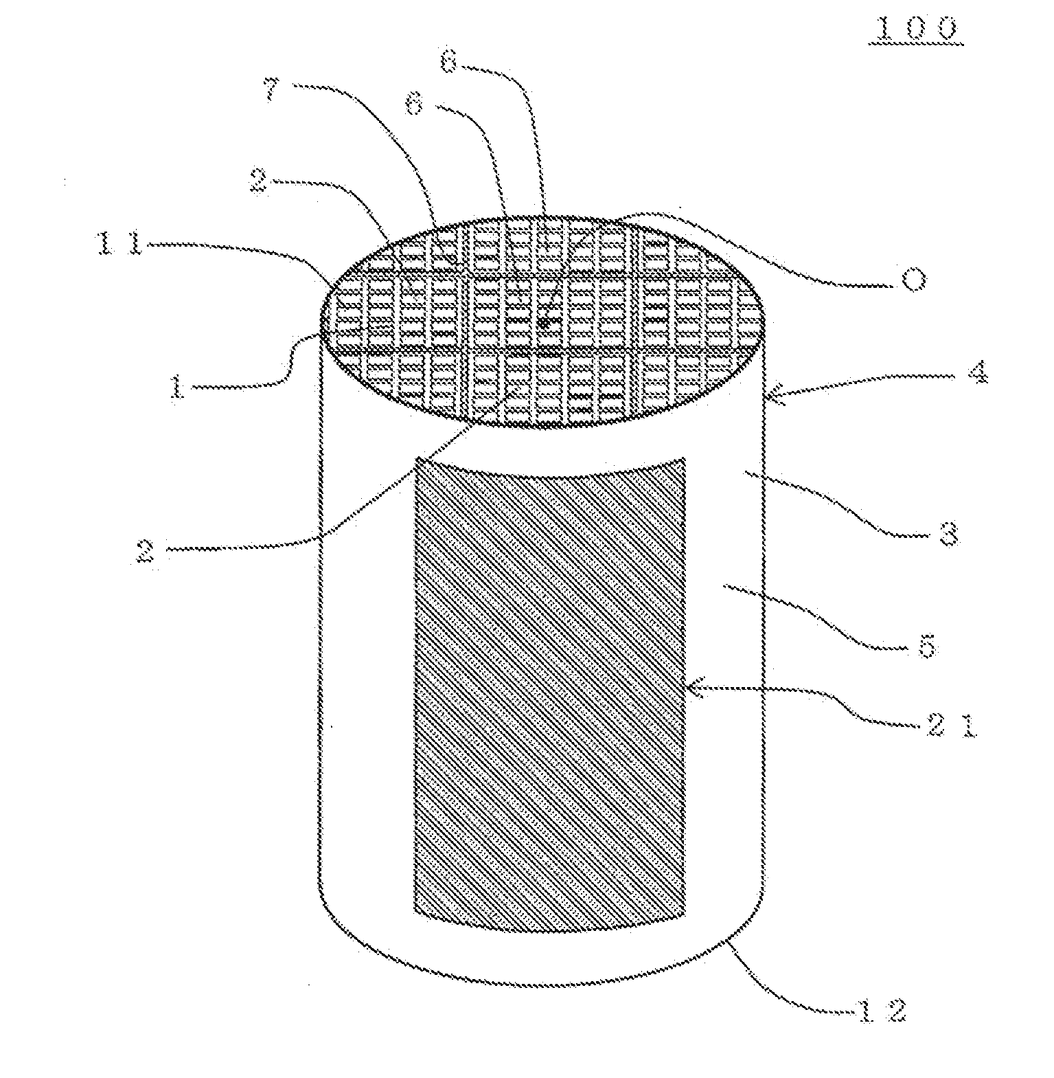
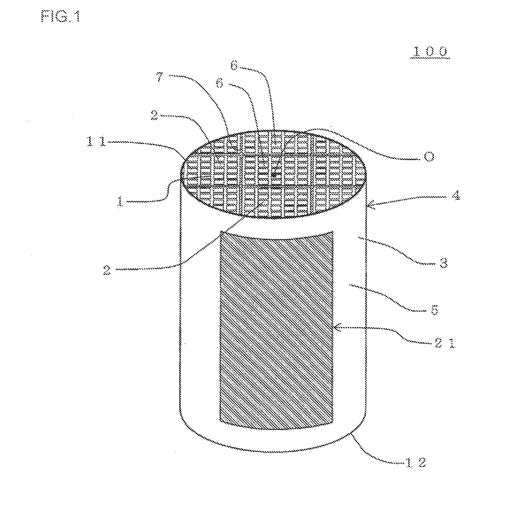
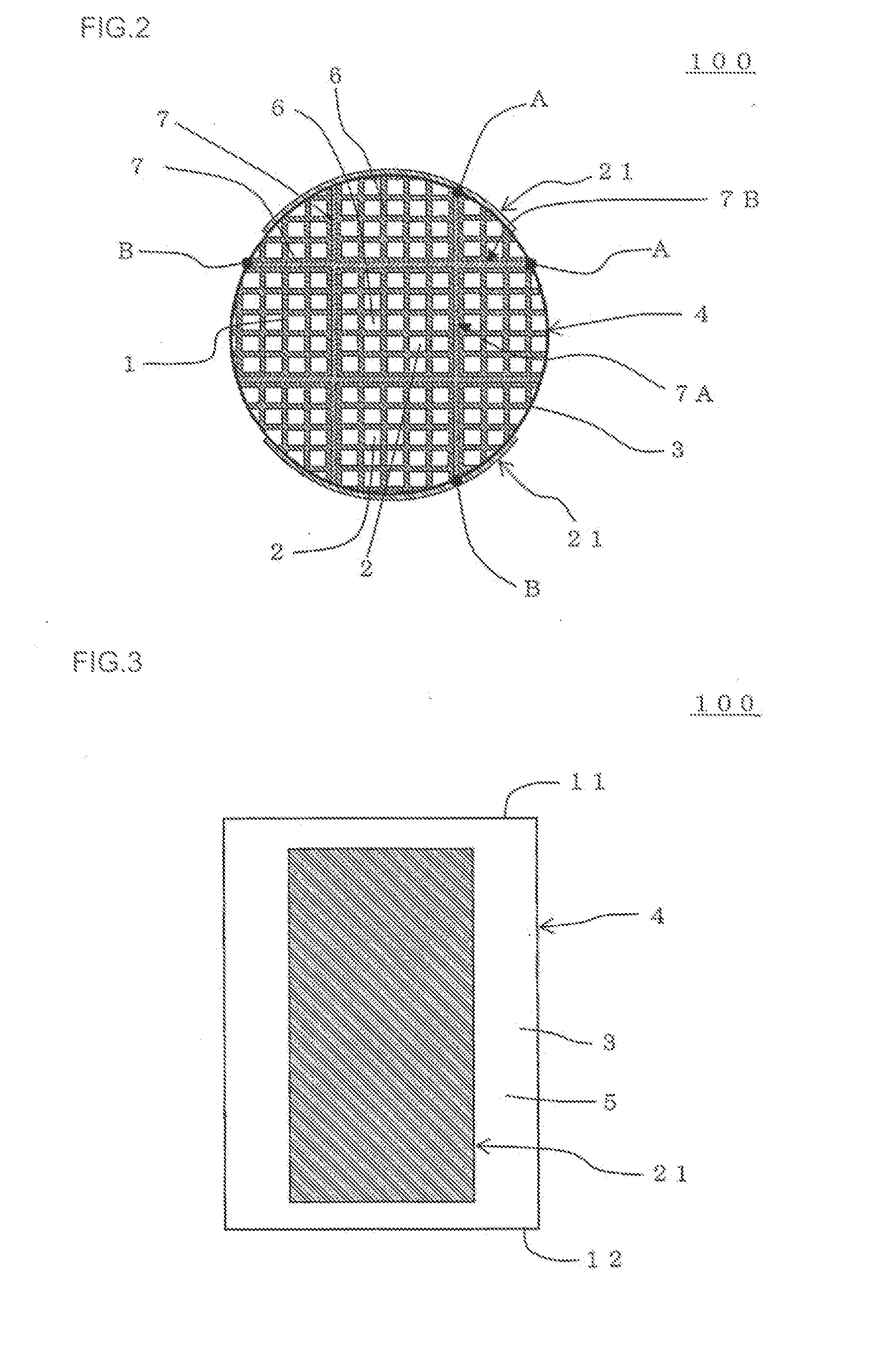
The present invention is a honeycomb structure that includes a heating element and electrode members. The honeycomb structure has a plurality of tubular honeycomb segments with porous partition walls defining cells as fluid channels, and the volume resistivity of each honeycomb segment is from 1 to 2000 Ωcm. The bonding layer that joins the honeycomb segments together has a volume resistivity of 2 to 2000 Ωcm. The electrode members formed as bands shape are placed on either side of the honeycomb segment bonded body. The honeycomb structure is made of a porous body with inorganic fibers and particles of silicon carbide bound by silicon. The honeycomb structure has superior thermal shock resistance and can function as a catalyst carrier and heater by applying a voltage.

Problems solved by technology

In a catalyst converter described in Patent Document 1, each of volume resistivity of a plurality of segments needs to be different from one another, and hence a load on production tends to be large.
Usually, as to conditions and the like for each use application, various problems and the like are present, and hence it has caused the problem that implementation is difficult.
In this case, if any elasticity does not exist in the bonding layer, there is a problem that partition walls which are low strength portions break down.
On the other hand, when the elasticity of the bonding layer is lowered, the stress is relaxed, but the strength is low, and hence it has caused a problem that the bonding layer is broken.

Method used


Image

  • Honeycomb structure
  • Honeycomb structure
  • Honeycomb structure

Examples


example 1

[0167]First, there was prepared a honeycomb forming raw material to prepare portions of honeycomb segments of a honeycomb segment bonded body. The honeycomb forming raw material was prepared by kneading 6 kg of silicon powder of 5 μm, 14 kg of silicon carbide powder of 30 μm, 1 kg of cordierite powder of 4 μm, 1.6 kg of methylcellulose, and 8 kg of water with a kneader.

[0168]Next, the obtained honeycomb forming raw material was kneaded in vacuum to obtain a kneaded material, and the obtained kneaded material was extruded into a honeycomb form, to obtain a honeycomb formed body. Next, the obtained honeycomb formed body was dried at 120° C. to obtain a honeycomb dried body.

[0169]Next, an electrode member forming raw material to form electrode members was prepared. The electrode member forming raw material was prepared by kneading silicon powder having an average particle diameter of 5 μm, silicon carbide powder having an average particle diameter of 50 μm, cordierite powder having an ...

example 2

[0179]The procedures of Example 1 were repeated except that a bonding material was prepared as follows, to prepare a honeycomb structure. Specifically, 84 g of silicon powder having an average particle diameter of 5 μm (a density of 2.33 g / cm3) was used. 103 g of silicon carbide powder having an average particle diameter of 43 μm (a density of 3.17 g / cm3) was used. 4 g of cordierite powder having an average particle diameter of 4 μm (a density of 2.65 g / cm3) was used. 12 g of alumina fibers (a density of 3.28 g / cm3) of Al2O3 / SiO2=80 / 20 (a mass ratio) were used. 10 g of resin powder (a density of 0.02 g / cm3) having an average particle diameter of 100 μm was used. 1 g of methylcellulose, 20 g of glycerin and 110 g of water were used. These materials were kneaded by a mixer, to prepare the bonding material. An average fiber diameter of inorganic fibers (i.e., alumina fibers) made of an oxide to be included in a bonding layer of the honeycomb structure of Example 2 was 8 μm and an avera...

example 3

[0180]The procedures of Example 1 were repeated except that a bonding material was prepared as follows, to prepare a honeycomb structure. Specifically, 82 g of silicon powder having an average particle diameter of 5 μm (a density of 2.33 g / cm3) was used. 78 g of silicon carbide powder having an average particle diameter of 16 μm (a density of 3.17 g / cm3) was used. 9 g of cordierite powder having an average particle diameter of 4 μm (a density of 2.65 g / cm3) was used. 35 g of alumina fibers (a density of 3.28 g / cm3) of Al2O3 / SiO2=80 / 20 (a mass ratio) were used. 10 g of resin powder (a density of 0.02 g / cm3) having an average particle diameter of 100 μm was used. 1 g of methylcellulose, 20 g of glycerin and 110 g of water were used. These materials were kneaded by a mixer, to prepare the bonding material. An average fiber diameter of inorganic fibers (i.e., alumina fibers) made of an oxide included in a bonding layer of the honeycomb structure of Example 3 was 8 μm and an average fibe...


PUM

PropertyMeasurementUnit
Temperatureaaaaaaaaaa
Lengthaaaaaaaaaa
Diameteraaaaaaaaaa

Abstract

To provide a honeycomb structure capable of using as a catalyst carrier, which suitably functions as a heater by applying a voltage, and where a bonding layer is hard to break; and including a honeycomb segment bonded body where honeycomb segments are bonded by bonding layer, and a pair of electrode members disposed on side surface of the bonded body, wherein the electrode members is formed into a band shape, in a cross section perpendicular to the cell extending direction, the one electrode member is disposed on an opposite side across the center of the bonded body with respect to another electrode member, and in at least a part of the bonding layer, inorganic fibers made of an oxide are included in a porous body where particles of silicon carbide are bound with silicon in a state where pores are held among the particles.

Description

[0001]The present application is an application based on JP-2013-075211 filed on Mar. 29, 2013 with the Japanese Patent Office, the entire contents of which are incorporated herein by reference.BACKGROUND OF THE INVENTION[0002]1. Field of the Invention[0003]The present invention relates to a honeycomb structure. More particularly, it relates to a honeycomb structure capable of being used as a catalyst carrier, which functions as a heater by applying a voltage.[0004]2. Background Art[0005]Heretofore, a honeycomb structure made of cordierite on which a catalyst is loaded has been used in a disposal of harmful substances in an exhaust gas discharged from a car engine. Moreover, a honeycomb structure formed by a sintered body of silicon carbide has been used in purification of the exhaust gas.[0006]When the exhaust gas is treated by the catalyst loaded on the honeycomb structure, it is necessary to raise a temperature of the catalyst to a predetermined temperature. However, at start of ...

Claims


Application Information

Patent Timeline
IPC IPC(8): B01J27/224
CPCB01J27/224C04B37/005C04B38/0019
Inventor KIKUCHI, YOSHIOHIDAKA, KENICHI
Owner NGK INSULATORS LTD
Learn More