Prosthetic Spinal Disc Replacement and Methods Thereof

a spinal disc and prosthesis technology, applied in the field of prosthetic spinal discs, can solve the problems of spinal disc displacement or damage, leg pain, loss of muscle control, persistent or disabling back pain, etc., to enhance stability of the stabilizing body, and facilitate the insertion of prosthetic discs

Active Publication Date: 2014-10-02
GLOBUS MEDICAL INC
View PDF2 Cites 32 Cited by
  • Summary
  • Abstract
  • Description
  • Claims
  • Application Information

AI Technical Summary

Benefits of technology

[0024]In a first configuration, the second elongated portion is substantially perpendicular to the first elongated portion to facilitate insertion of the prosthetic disc. A distal end of the second elongated portion may be pointed or sharped to ease insertion into the vertebrae. In a second configuration, the second elongated portion may be compressed closer to the first surface of the first or second endplate to secure the prosthetic disc to the first or second vertebral body. For example, in the second configuration, the second elongated portion may be provided at an angle less than 90° relative to the first elongated portion (e.g., about)45-80°. A portion of the second elongated portion may be serrated, for example, to enhance stability of the stabilizing body in the second, compressed configuration. A transition between the first and second configurations may occur when the stabilizing body is at least partially formed from a shape memory alloy, such as a temperature sensitive shape memory alloy, and the temperature of the stabilizing body reaches body temperature. For example, the shape memory alloy may include a copper-aluminum-nickel alloy or a nickel-titanium alloy (i.e., Nitinol).
[0025]The first surfaces of the first and second endplates may be smooth and do not include keels or the like. By eliminating the keels and the need for cutting an opening in the vertebral endplate for a keel and by leaving the vertebral endplate intact, the chances of fracturing the endplate is reduced, and the possibility of additional bleeding on the endplates due to extensive preparation is reduced. Removing the keels also eliminates the need to have high speed mills to prepare the vertebral endplates, which adds to surgical time and complexity.

Problems solved by technology

The spinal disc may be displaced or damaged due to trauma, disease, degenerative defects, or wear over an extended period.
The mass of a herniated or “slipped” nucleus tissue can compress a spinal nerve, resulting in leg pain, loss of muscle control, or even paralysis.
As these overlapping laminated plies of the annulus begin to buckle and separate, either circumferential or radial annular tears may occur, which may contribute to persistent or disabling back pain.
Adjacent, ancillary spinal facet joints will also be forced into an overriding position, which may create additional back pain.
Whenever the nucleus tissue is herniated or removed by surgery, the disc space will narrow and may lose much of its normal stability.
While this treatment alleviates the pain, all discal motion is lost in the fused segment.
Ultimately, this procedure places a greater stress on the discs adjacent to the fused segment as they compensate for lack of motion, perhaps leading to premature degeneration of those adjacent discs.
Many of the current designs for prosthetic discs are large and inflexible.
In addition, prosthetic disc sizes and other parameters limit the approach a surgeon may take to implant the devices.
For example, many of these devices require an anterior implantation approach as the barriers presented by the lamina and, more importantly, the spinal cord and nerve rootlets during posterior or posterior lateral implantation is difficult to avoid.
Anterior implantation involves numerous risks during surgery.
Various organs present physical obstacles as the surgeon attempts to access the damaged disc area from the front of the patient.
These greater vessels (the aorta and vena cava) risk exposure and injury during surgery.
One risk to the patient from an anterior approach is that their organs may be inadvertently damaged during the procedure.
Another risk to the patient from an anterior approach is that their greater vessels may be injured during surgery.
Despite this advantage, a posterior approach raises other difficulties that have discouraged its use.
For instance, a posterior approach can introduce a risk of damaging the spinal cord.
One drawback to this method is that the removal of a facet joint may lead to instability of the spine.
Due to limitations on the available space, disc replacements may only provide one type of connecting mechanism to a holder.
Because disc replacement implants move during normal operation, there is a concern, especially during removal, that the discs may be come unaligned or separated and difficult to remove.
The keels need a chisel to cut through the vertebral endplates, which may cause bleeding as well as concerns regarding the fusion of a motion preserving device.

Method used


Image

  • Prosthetic Spinal Disc Replacement and Methods Thereof
  • Prosthetic Spinal Disc Replacement and Methods Thereof
  • Prosthetic Spinal Disc Replacement and Methods Thereof

Examples


Embodiment Construction

[0063]Embodiments of the invention will now be described. The following detailed description of the invention is not intended to be illustrative of all embodiments. In describing embodiments of the present invention, specific terminology is employed for the sake of clarity. However, the invention is not intended to be limited to the specific terminology so selected. It is to be understood that each specific element includes all technical equivalents that operate in a similar manner to accomplish a similar purpose.

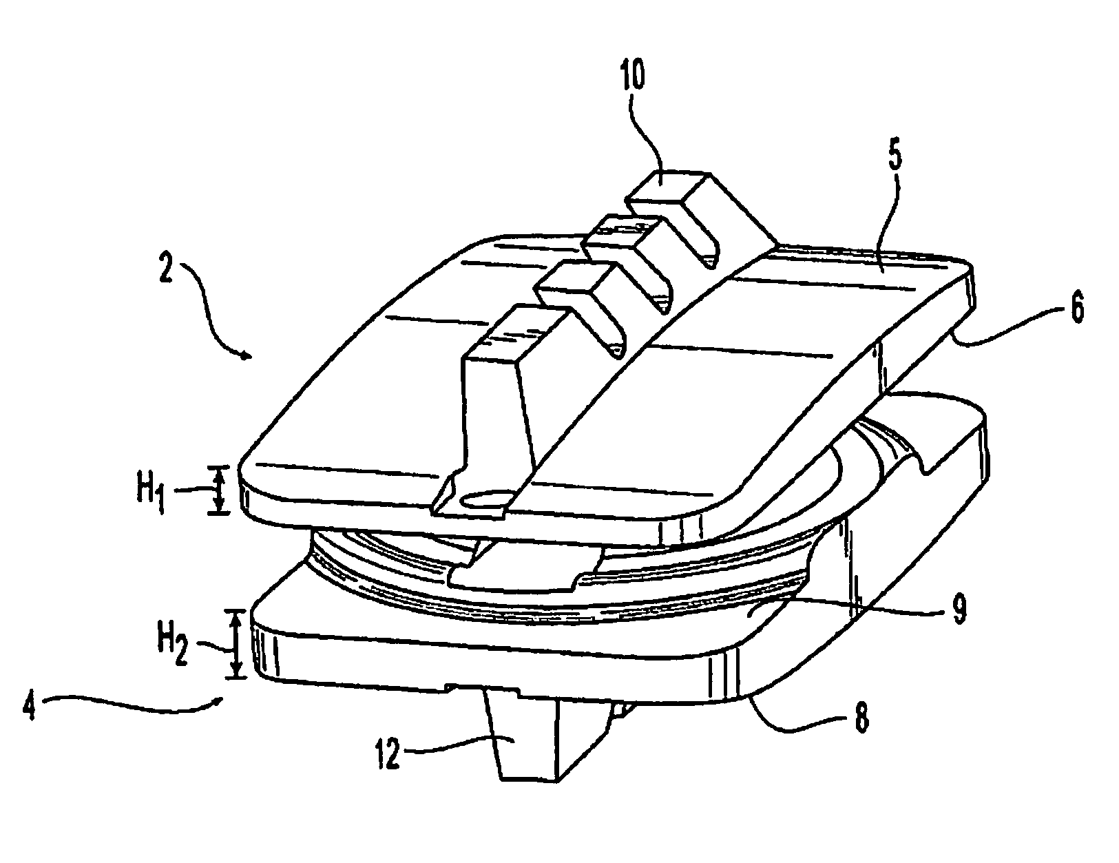
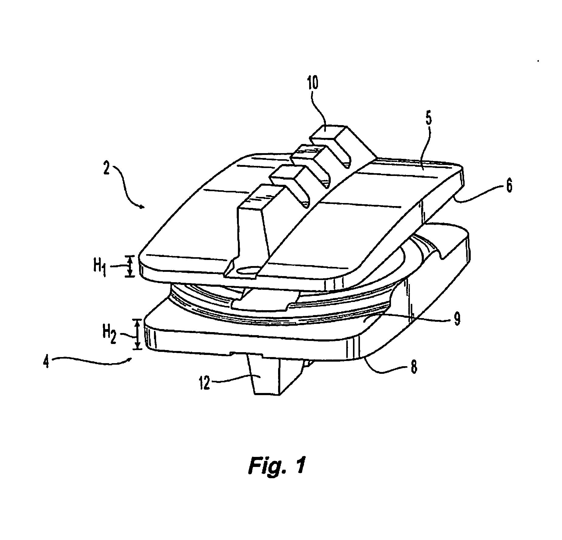
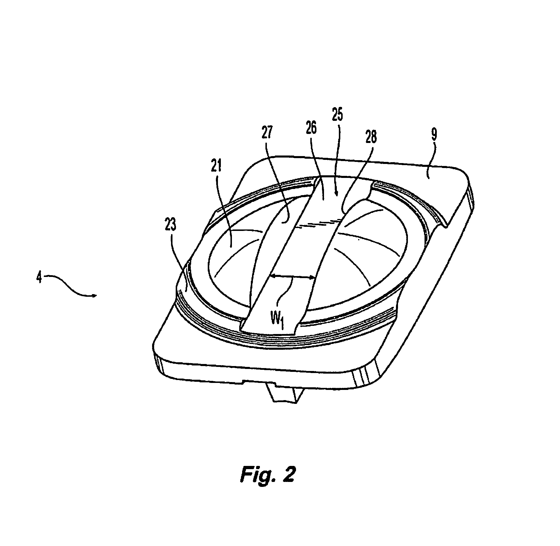
[0064]The present disclosure relates generally to prosthetic spinal discs for replacing a damaged disc between two vertebrae of a spine. In particular, the intervertebral prosthetic discs are provided with two connections for facilitating implantation and removal, and intervertebral prosthetic discs which offer primary and secondary stability, for example, in the form of L-shaped pins or spikes. Various instruments, aids, and other devices for implanting the various prosthe...


PUM

PropertyMeasurementUnit
angleaaaaaaaaaa
angleaaaaaaaaaa
heightaaaaaaaaaa

Abstract

The present invention relates generally to a prosthetic spinal disc for replacing a damaged disc between two vertebrae of a spine and methods for inserting said discs. The intervertebral prosthetic discs are provided with connections for facilitating implantation and removal and features which enhance primary and secondary stability over time.

Description

CROSS REFERENCE TO RELATED APPLICATIONS[0001]This application is a continuation-in-part of U.S. Ser. No. 13 / 889,876, filed May 8, 2013, which is a continuation of U.S. Ser. No. 11 / 366,390, filed Mar. 3, 2006, now U.S. Pat. No. 7,811,329, which is a continuation-in-part of U.S. Ser. No. 11 / 318,438, filed Dec. 28, 2005, now U.S. Pat. No. 7,713,304, which is a continuation-in-part of U.S. Ser. No. 11 / 246,149, filed Oct. 11, 2005, now U.S. Pat. No. 8,167,948, which claims priority to U.S. Ser. No. 10 / 909,210, filed Jul. 30, 2004, now U.S. Pat. No. 7,641,666, U.S. Ser. No. 10 / 827,642, filed Apr. 20, 2004, now U.S. Pat. No. 7,621,956, and U.S. Provisional Application 60 / 491,271, filed Jul. 31, 2003. Each of these references is incorporated herein by reference in their entireties.FIELD OF THE INVENTION[0002]The disclosure relates to a prosthetic spinal disc for fully or partially replacing a damaged disc between two vertebrae of a spine.BACKGROUND OF THE INVENTION[0003]The vertebrate spine...

Claims


Application Information

Patent Timeline
Patent Type & Authority Applications(United States)
IPC IPC(8): A61F2/44
CPCA61F2/442A61B17/1735A61F2/4611A61F2002/30616A61F2002/30649A61F2002/30662A61F2002/30769A61F2002/30772A61F2002/30878A61F2002/30884A61F2002/30899A61F2002/3092A61F2002/30935A61F2002/443A61F2002/448A61F2002/4627A61F2002/4629A61F2002/4681A61F2220/0025A61F2220/0033A61F2220/0041A61F2220/0058A61F2/4684A61B2017/0046A61B2017/0256A61F2002/30014A61F2002/30113A61F2002/30125A61F2002/30153A61F2002/30166A61F2002/302A61F2002/30224A61F2002/30365A61F2002/30387A61F2002/30433A61F2002/30451A61F2002/30471A61F2002/30517A61F2002/30545A61F2002/30563A61F2002/30568A61F2002/30571A61F2002/30579A61F2002/30594A61F2002/30601A61F2002/30604A61F2220/0091A61F2230/0006A61F2230/0008A61F2230/0019A61F2230/0028A61F2230/0065A61F2230/0069A61F2250/001A61F2250/0018A61F2310/00407A61F2310/00796A61B17/1604A61B17/1671A61F2/4405A61F2/4425A61B17/1757A61F2002/30841A61F2/44
Inventor BALASUBRAMANIAN, ANANDDWYER, EDPERETZ, DAVIDANKNEY, DAVIDRHODA, WILLIAM SPAUL, DAVID CANGELUCCI, CHRISTOPHER
Owner GLOBUS MEDICAL INC
Why Eureka
Try Eureka