Method and system for engine control

a technology of engine control and system, applied in the direction of electrical control, process and machine control, instruments, etc., can solve the problems of degrading exhaust emissions, insufficient time for mixing of injected fuel and air in the cylinder, and generating more particulate matter emissions (or soot), so as to increase the heat of vaporization, increase the octane, and increase the charge cooling effect

a technology of engine control and system, applied in the direction of electrical control, process and machine control, instruments, etc., can solve the problems of degrading exhaust emissions, insufficient time for mixing of injected fuel and air in the cylinder, and generating more particulate matter emissions (or soot), so as to increase the heat of vaporization, increase the octane, and increase the charge cooling effect

US20140297162A1Active Publication Date: 2014-10-02FORD GLOBAL TECH LLC

Image

  • Method and system for engine control
  • Method and system for engine control
  • Method and system for engine control

Examples


Embodiment Construction

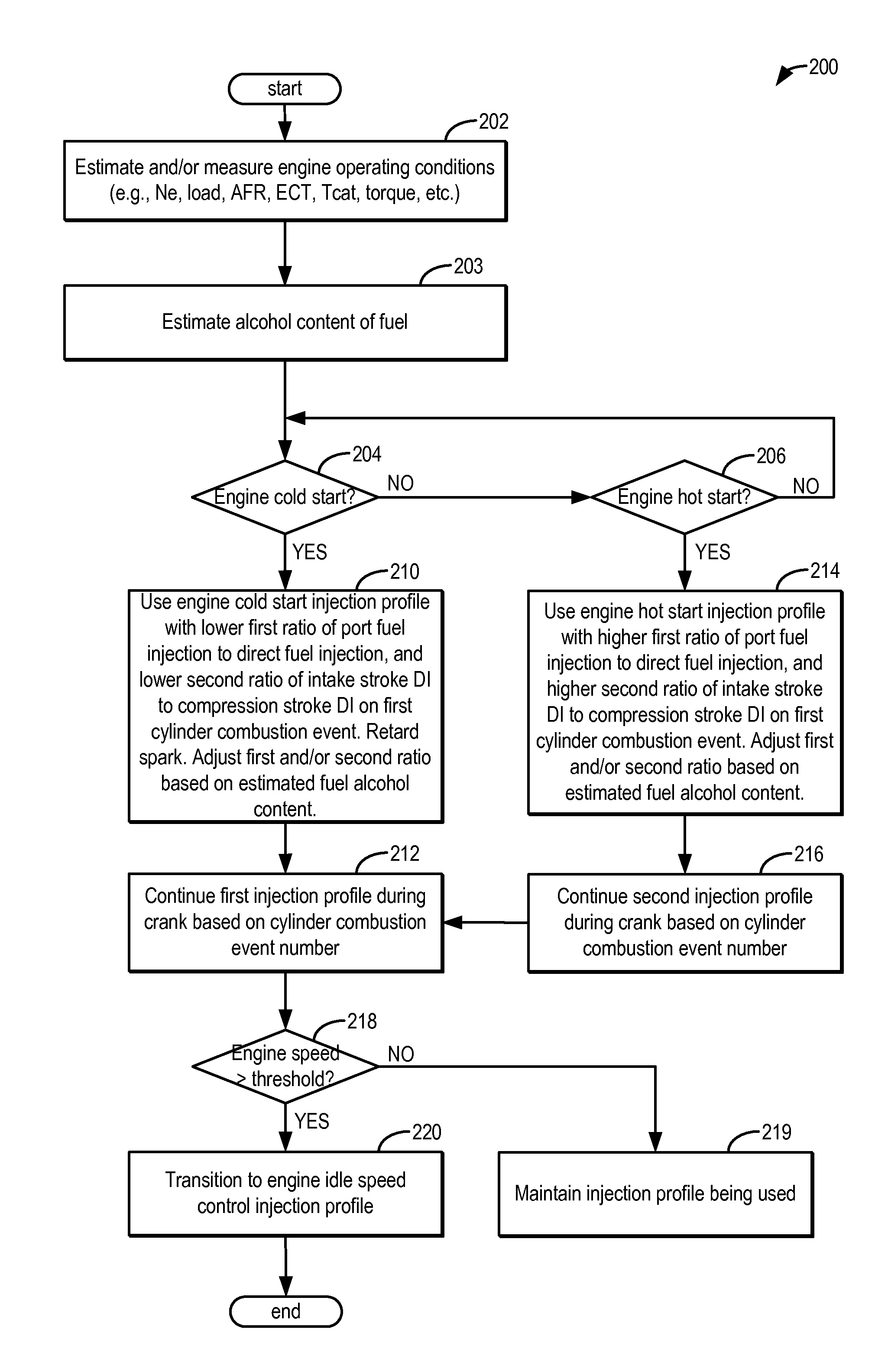
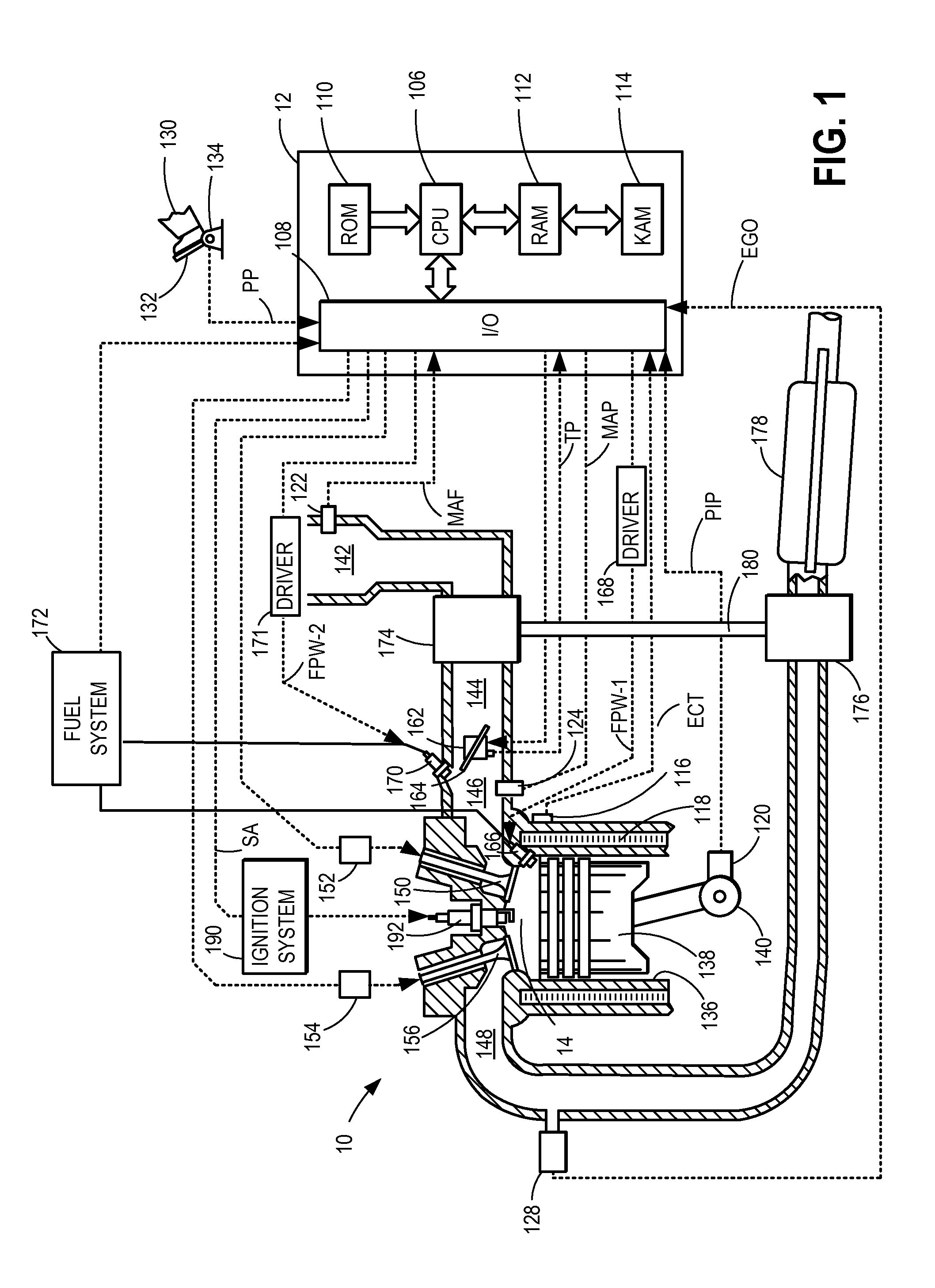
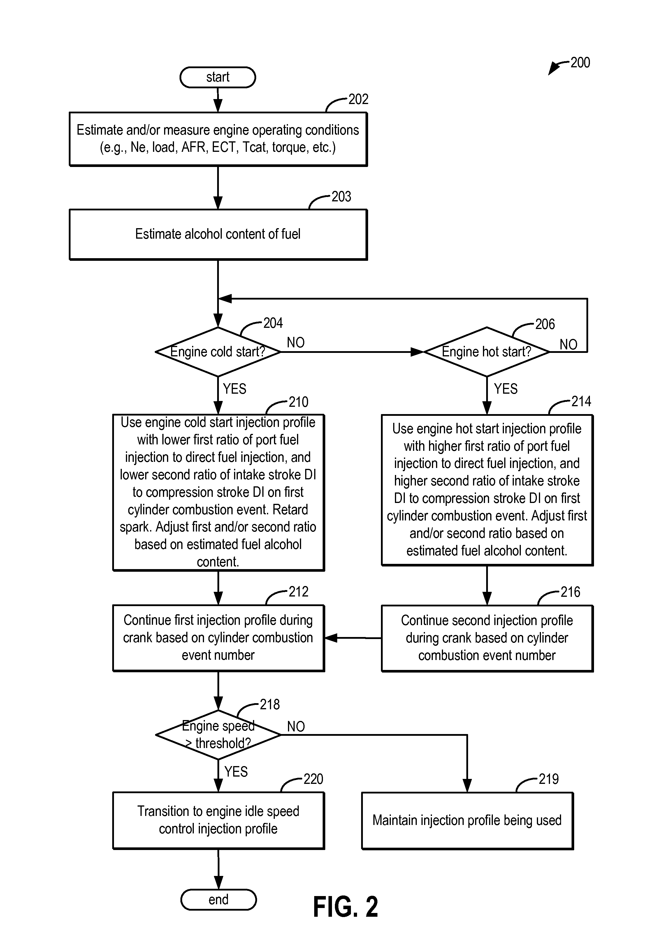
[0013]The following description relates to systems and methods for adjusting an engine fuel injection, such as in the engine system of FIG. 1, during engine start and crank, based on an alcohol content of the injected fuel, to reduce a soot load of the engine. An engine controller may perform a control routine, such as the routine of FIG. 2, to adjust a fuel injection profile, including an amount of fuel port injected to a cylinder and an amount of fuel direct injected over multiple injections into the cylinder, during an engine start and during cranking based on the composition of the fuel, such as based on the alcohol content of the fuel. The profile may be further adjusted based on each of an exhaust catalyst temperature and a cylinder event number so as to expedite catalyst activation while reducing exhaust PM emissions and without degrading combustion stability. By adjusting the fuel injection profile from a profile having a relatively higher amount of port injection during eng...


PUM


Abstract

Methods and systems are provided for controlling exhaust emissions by adjusting an injection profile for fuel injected into an engine cylinder from a plurality of fuel injectors during engine start and crank. By splitting injection of fuel during start so that a portion of fuel is port injected and a remaining portion is direct injected as one or multiple injections, the soot load of the engine can be reduced and fuel economy can be improved. The injections are adjusted based on the alcohol content of the injected fuel to take advantage of the charge cooling properties of the fuel.

Description

FIELD[0001]The present application relates to methods and systems for controlling fuel injection in an engine system coupled to a flex-fuel vehicle.BACKGROUND AND SUMMARY[0002]Engines may be configured with direct fuel injectors that inject fuel directly into a combustion cylinder (direct injection), and / or with port fuel injectors that inject fuel into a cylinder port (port fuel injection). In flex-fuel vehicles, a flexible multiple-fuel engine can operate with fuel of varying composition by delivering different proportions of the variable fuel to different injectors. For example, direct injection of an ethanol fuel may be used to take advantage of the increased charge cooling effects of the alcohol fuel's higher heat of vaporization and increased octane. This helps to address knock limitations, especially under boosted conditions.[0003]Direct injected engines, however, also generate more particulate matter emissions (or soot) due to diffuse flame propagation wherein fuel may not a...

Claims


Application Information

Patent Timeline
02 Oct 2014
Publication
US20140297162A1
IPC
F02D41/30; F02D43/04
CPC
F02D43/04; F02D41/3094; F02D41/0025; F02D41/064; F02D41/065; F02D41/402; F02D2200/0612; Y02T10/40
Inventors
SURNILLA, GOPICHANDRA; SCHWOCHERT, STEVEN